Discharge apparatus, material application method, manufacturing method for color filter substrate, manufacturing method for electroluminescence display apparatus, manufacturing method for plasma display apparatus, and wiring manufacturing method
- Summary
- Abstract
- Description
- Claims
- Application Information
AI Technical Summary
Benefits of technology
Problems solved by technology
Method used
Image
Examples
first embodiment
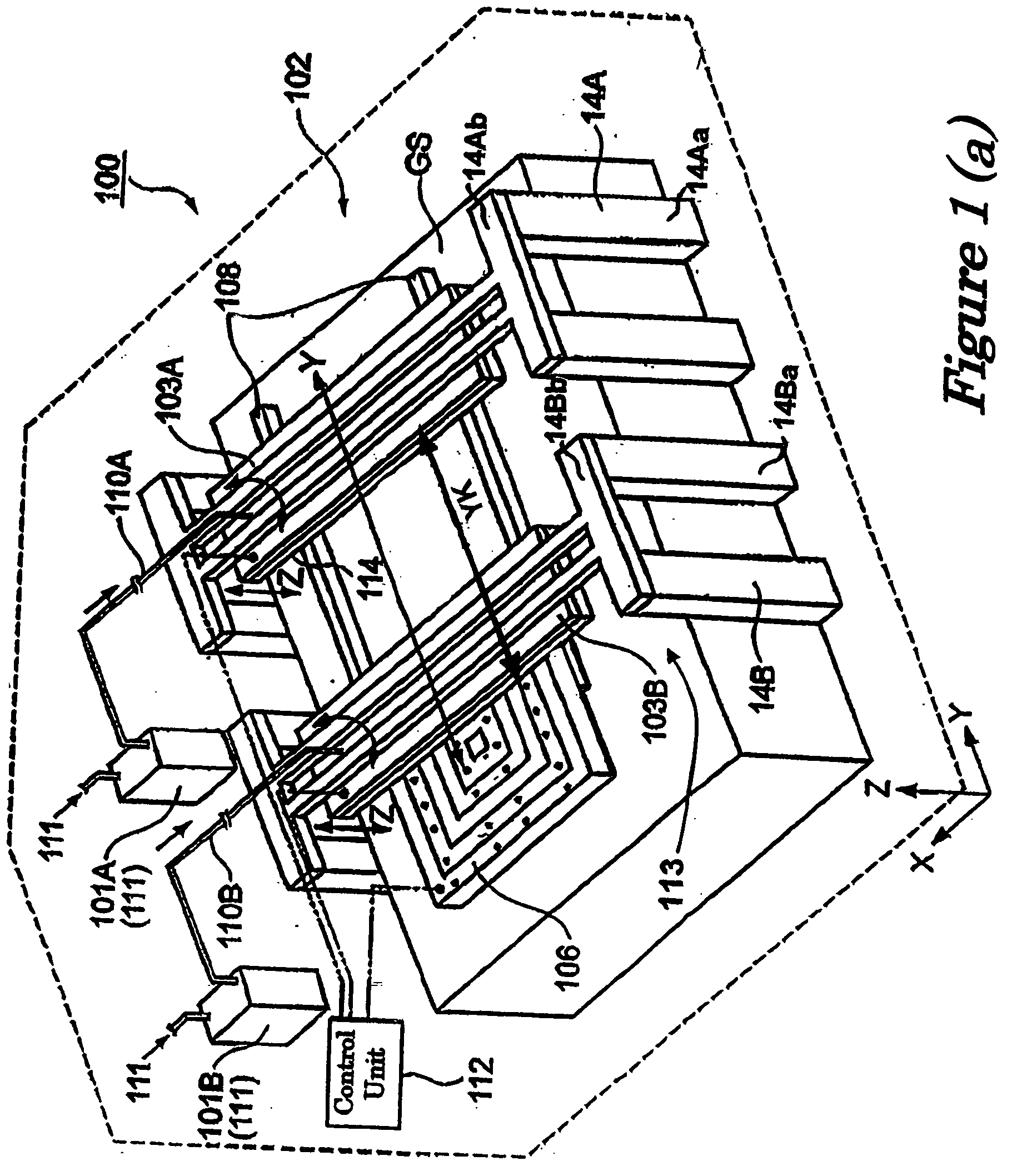
[0064] A discharge apparatus in accordance with the first embodiment of the present invention is described below in the following order. [0065] A. Overall configuration of the discharge apparatus [0066] B. Head [0067] C. Control unit [0068] D. Discharge head unit [0069] E. Application step
[0070] A. Overall Configuration of the Discharge Apparatus
[0071] The discharge apparatus 100 shown in FIG. 1 has two tanks 101A and 101B, a tube 110A, a tube 110B, and a discharge scanning unit 102. Both of the tanks 101A and 101B store a liquid material 111. The tubes 110A and 110B each feed liquid material 111 from the tanks 101A and 101B to the discharge scanning unit 102. The discharge scanning unit 102 has a stage 106, a first discharge head unit 103A, a second discharge head unit 103B, a scanning unit 113, a ground stage GS, and a control unit 112.
[0072] Both the first discharge head unit 103A and the second discharge head unit 103B are formed so as to discharge droplets of the liquid mate...
second embodiment
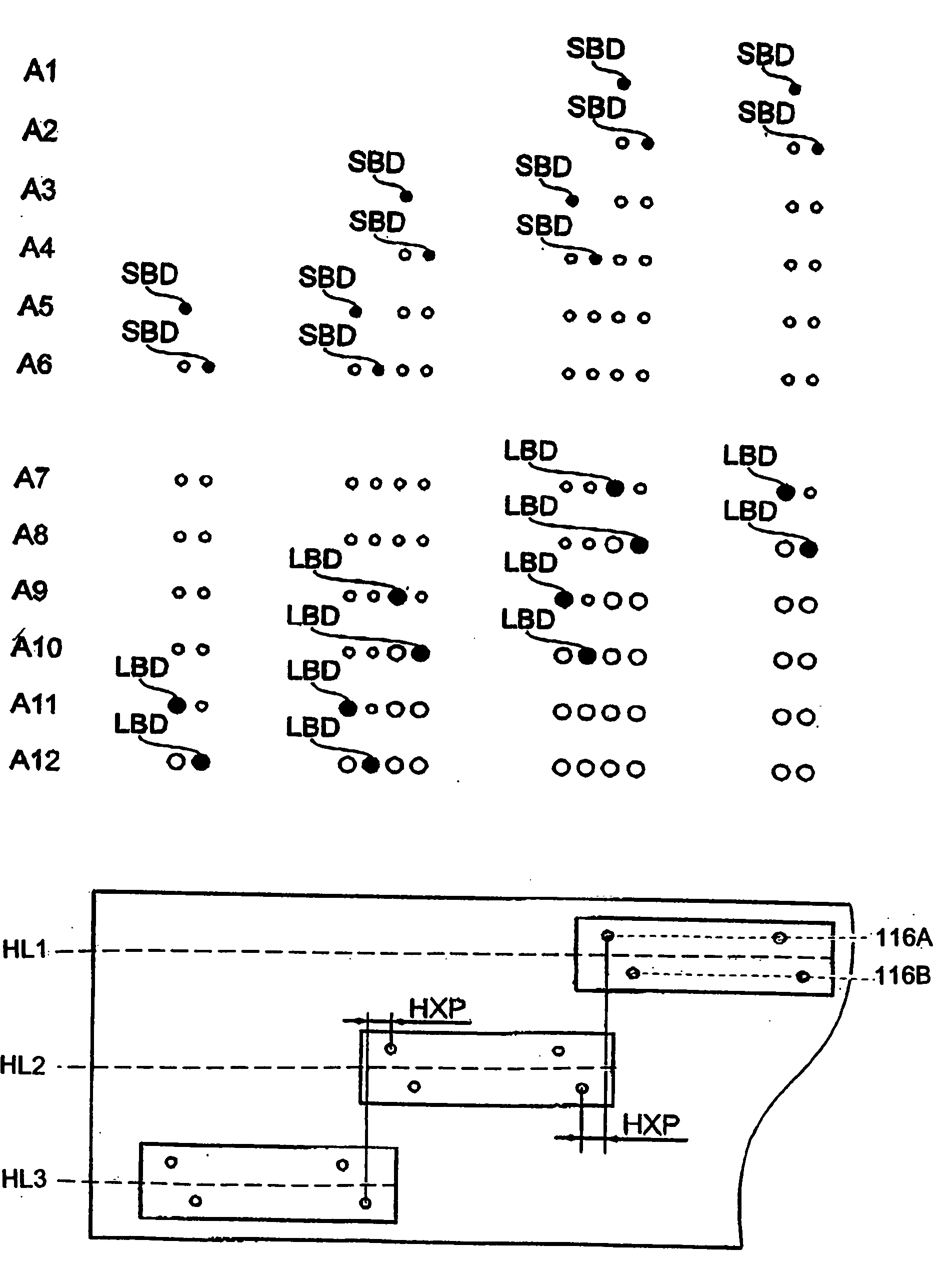
[0138] Referring now to FIGS. 9-10 a discharge apparatus in accordance with a second embodiment will now be explained. The configuration of the discharge apparatus of the second embodiment of the present embodiment is the same as the configuration of the discharge apparatus 100 of the first embodiment, except that the arrangement pattern of the discharge nozzles 118T in the first discharge head unit 103C and the arrangement pattern of the discharge nozzles 118T in the second discharge head unit 103D differ from those of the first and second discharge head units 103A and 103B in the first embodiment. In view of the similarity between the first and second embodiments, the parts of the second embodiment that are identical to the parts of the first embodiment will be given the same reference numerals as the parts of the first embodiment.
[0139] The first discharge head unit 103C is separated from the second discharge head unit 103D by a predetermined distance YK in the Y-axis direction,...
third embodiment
[0171] Referring now to FIGS. 11-12, a discharge apparatus in accordance with a second embodiment will now be explained. The configuration of the discharge apparatus of the present embodiment is the same as that of the discharge apparatus of the second embodiment, except that the arrangement pattern of the discharge nozzles 118T in the first discharge head unit 103E and the second discharge head unit 103F differ from that of the first and second discharge head units 103C and 103D of the second embodiment. In view of the similarity between the first and second embodiments, the parts of the second embodiment that are identical to the parts of the first embodiment will be given the same reference numerals as the parts of the first embodiment.
[0172] In the second embodiment, the plurality of head groups 114G in the first discharge head unit 103C is arranged in the X-axis direction as a single row (FIGS. 9 and 10). In the third embodiment, each of the plurality of head groups 114G has a...
PUM
| Property | Measurement | Unit |
|---|---|---|
| Time | aaaaa | aaaaa |
| Area | aaaaa | aaaaa |
| Velocity | aaaaa | aaaaa |
Abstract
Description
Claims
Application Information
 - R&D
- Intellectual Property
- Life Sciences
- Materials
- Tech Scout
- Unparalleled Data Quality
- Higher Quality Content
- 60% Fewer Hallucinations
Browse by: Latest US Patents, China's latest patents, Technical Efficacy Thesaurus, Application Domain, Technology Topic, Popular Technical Reports.
© 2025 PatSnap. All rights reserved.Legal|Privacy policy|Modern Slavery Act Transparency Statement|Sitemap|About US| Contact US: help@patsnap.com


