
Inkjet printer

a technology of inkjet printers and air purging passages, which is applied in the direction of printing and inking apparatus, etc., can solve the problems of large ink consumption, difficult purging of air from air purging passages branching off from individual ink flow passages, etc., and achieves comparatively low ink supply pressure, and easy purging of air.

Active Publication Date: 2005-07-21
BROTHER KOGYO KK
View PDF7 Cites 33 Cited by
  • Summary
  • Abstract
  • Description
  • Claims
  • Application Information

AI Technical Summary

Benefits of technology

[0006] It is an object of the present invention to provide an inkjet printer capable of readily discharging air from the inside of a flow passage.
[0020] According to still another aspect of the invention, there is provided, in a state where the air purging passage is released, flow passage resistance of the air purging passage is lower than a total of flow passage resistance of a portion of the ink supply flow passage located downstream of the position where the air purging passage branches off from the ink supply flow passage and flow passage resistance of the individual ink flow passages. Consequently, the ink in the ink supply flow passage easily flows from the branch position toward the air purging passage having flow passage resistance lower than that of the individual ink flow passages. Therefore, the air can be purged readily even when the ink supply pressure is comparatively low.

Problems solved by technology

Purging air from such air purging passages branching off from the individual ink flow passages is not easy.
In the course of such purging operation, a great quantity of ink is consumed.

Method used


Image

  • Inkjet printer
  • Inkjet printer
  • Inkjet printer

Examples


first embodiment

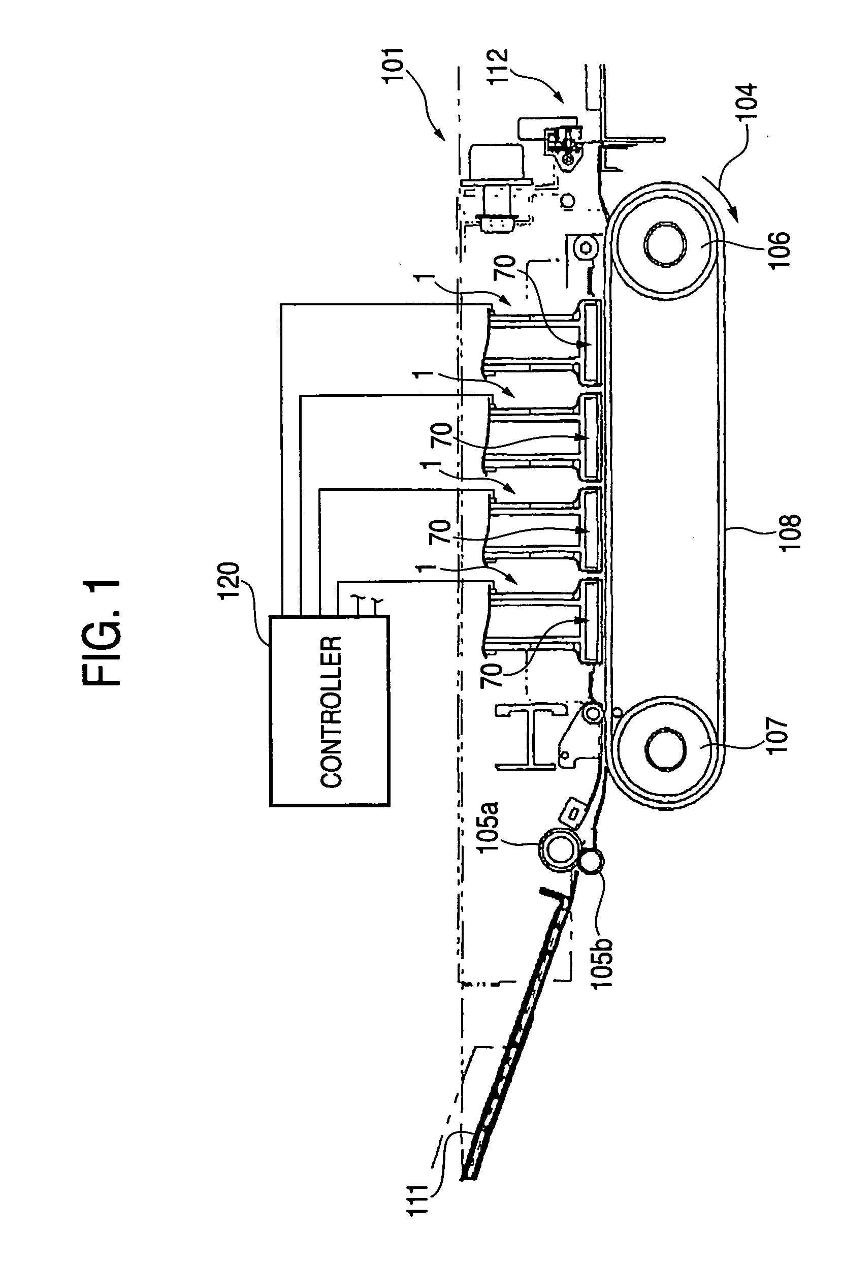
[0039]FIG. 1 is a schematic diagram of an inkjet printer according to the present invention. An inkjet printer 101 is a color inkjet printer having four inkjet heads 1. The inkjet printer 101 is configured such that a paper feed section 111 is provided on the left side of the printer in the drawing and such that a paper output section 112 is provided on the right side of the same in the drawing.

[0040] A paper transport path along which paper is transported from the paper feed section 111 toward the paper output section 112 is formed in the inkjet printer 101. A pair of feed rollers 105a, 105b for transporting in a nipped manner paper which is a recording medium are disposed at a position immediately downstream of the paper feed section 111. Paper is transported from left to right in the drawing by the pair of feed rollers 105a, 105b. Two belt rollers 106, 107 and a transport belt 108 endlessly wrapped around the rollers 106, 107 are disposed at an intermediate position of the paper ...

second embodiment

[0098] In the second embodiment, the air purging passages 67A is branched from two locations along the way from the opening section 5b of the manifold 5 to the sub-manifolds 5a. However, the number of branches is not limited to two. Further, the air purging passage may be branched off from the plurality of respective sub-manifolds 5a branched from the manifold 5.

[0099] There will now be described a third embodiment of the present invention. The third embodiment is different from the second embodiment in that an air purging flow passage 67B is provided. In other respects, the second embodiment is the same as the second embodiment.

[0100] In the following descriptions, the same reference numerals are assigned to elements having the same configurations as those described in connection with the second embodiment, and their explanations are omitted, to the extent appropriate.

[0101] As shown in FIG. 16, there are formed two elongated holes 28d, 28e which are in communication with a manif...

third embodiment

[0108] In the third embodiment, the air purging passages 67B is branched from two locations along the way from the opening section 5b of the manifold 5 to the sub-manifolds 5a. However, the number of branches is not limited to four. Further, the air purging passage may be branched off from the plurality of respective sub-manifolds 5a branched from the manifold 5.


PUM


Abstract

An inkjet printer has a reservoir unit including an ink supply port to which ink is supplied from the outside and an ink reservoir for storing the ink supplied from the ink supply port. Further, the inkjet printer has an air purging passage branched off from an area of an ink supply flow passage extending from the ink supply port to a manifold via the ink reservoir. The area is located downstream with respect to a filter; and an air purging valve capable of opening or closing the air purging passage. The air in the ink supply passage can be readily purged from the air purging passage.

Description

BACKGROUND OF THE INVENTION [0001] 1. Field of the Invention [0002] The present invention relates to an inkjet printer which effects printing by ejecting ink on a recording medium. [0003] 2. Description of the Related Art [0004] An inkjet head of an inkjet printer ejects ink from a nozzle remaining in communication with respective pressure chambers, by distributing ink supplied from an ink supply port to the plurality of pressure chambers from a common ink chamber and selectively imparting pulse-like pressure to the respective pressure chambers. When air is trapped in an ink flow passage. which is formed in an inkjet head and extends from the ink supply port to the nozzle. the air adheres to an interior wall surface of the flow passage. As a result, a pressure wave imparted to ink by a pressure chamber fails to properly propagate through the flow passage, possibly deteriorating an ink-ejecting characteristic of the nozzle. Therefore, there is proposed an inkjet head having an air-di...

Claims


Application Information

Patent Timeline
Patent Type & Authority Applications(United States)
IPC IPC(8): B41J2/14B41J2/175B41J2/19
CPCB41J2/14209B41J2/17513B41J2/19B41J2002/14217B41J2202/20B41J2002/14306B41J2002/14403B41J2002/14419B41J2002/14459B41J2002/14225B41J2002/14491B41J2002/14362
Inventor HIROTA, ATSUSHIWATANABE, HIDETOSHICHIKAMOTO, TADANOBU
Owner BROTHER KOGYO KK
Features
  • Generate Ideas
  • Intellectual Property
  • Life Sciences
  • Materials
  • Tech Scout
  • Unparalleled Data Quality
  • Higher Quality Content
  • 60% Fewer Hallucinations
Learn More