Turbine airfoil cooling system with axial flowing serpentine cooling chambers

a cooling system and turbine airfoil technology, applied in the direction of liquid fuel engines, machines/engines, mechanical equipment, etc., can solve the problems of reducing the useful life of the turbine blade, the likelihood of failure, and localized hot spots, so as to increase the cooling fluid air pressure, increase the cooling fluid pressure, and enhance the blade hcf capability

Inactive Publication Date: 2008-02-28
SIEMENS ENERGY INC
View PDF18 Cites 21 Cited by
  • Summary
  • Abstract
  • Description
  • Claims
  • Application Information

AI Technical Summary

Benefits of technology

[0013]Yet another advantage of this invention is that the cooling flow originates from the root at the leading and trailing edges and proceeds towards the tip section, thereby providing cooler leading and trailing edges proximate to the platform, thus enhancing blade HCF capability.
[0014]Another advantage of this invention is that centrifugal forces create a centrifugal pumping effect on the cooling fluids in the cooling system and thereby increase the cooling fluid air pressure as it moves radially farther from the root of the airfoil. The increased pressure offsets the pressure loss attributable to turn loss and friction loss in the serpentine cooling channels.
[0015]Still another advantage of this invention is that the increased pressure due to the centrifugal pumping effect enables a lower cooling air supply pressure to be used, which yields a lower leakage flow around the blade attachment and reduced temperature cooling fluid.
[0016]Another advantage of this invention is that the cooling fluids impinge on the leading and trailing edges, thereby creating a very high internal heat transfer coefficient. In addition, each fluid at the leading and trailing edge turns causes a momentum change, which results in an increase of heat transfer coefficient.
[0017]Yet another advantage of this invention is that the suction and pressure side serpentine cooling channels can be tailored to accommodate the heat loads on the exterior surfaces of the airfoil. The channel width for the pressure side serpentine cooling channel may differ from the suction side serpentine cooling channel and thereby change the cooling fluid flow between the pressure and suction side serpentine cooling channels. The channel widths of the legs of the suction and pressure side cooling channels may be varied axially, which impacts the cooling flow mass flux and alters the cooling capability and metal temperature along the flow path.
[0018]Another advantage of this invention is that the suction side or the pressure side serpentine cooling channels may have a convergent nozzle geometry immediately upstream from the cooling fluid exit orifice. Such configuration enhances the airfoil leading and trailing edge impingement jet velocity and increases the impingement heat transfer coefficient and airfoil edge cooling.

Problems solved by technology

In addition, turbine blades often contain cooling systems for prolonging the life of the blades and reducing the likelihood of failure as a result of excessive temperatures.
However, centrifugal forces and air flow at boundary layers often prevent some areas of the turbine blade from being adequately cooled, which results in the formation of localized hot spots.
Localized hot spots, depending on their location, can reduce the useful life of a turbine blade and can damage a turbine blade to an extent necessitating replacement of the blade.

Method used


Image

  • Turbine airfoil cooling system with axial flowing serpentine cooling chambers
  • Turbine airfoil cooling system with axial flowing serpentine cooling chambers
  • Turbine airfoil cooling system with axial flowing serpentine cooling chambers

Examples


Embodiment Construction

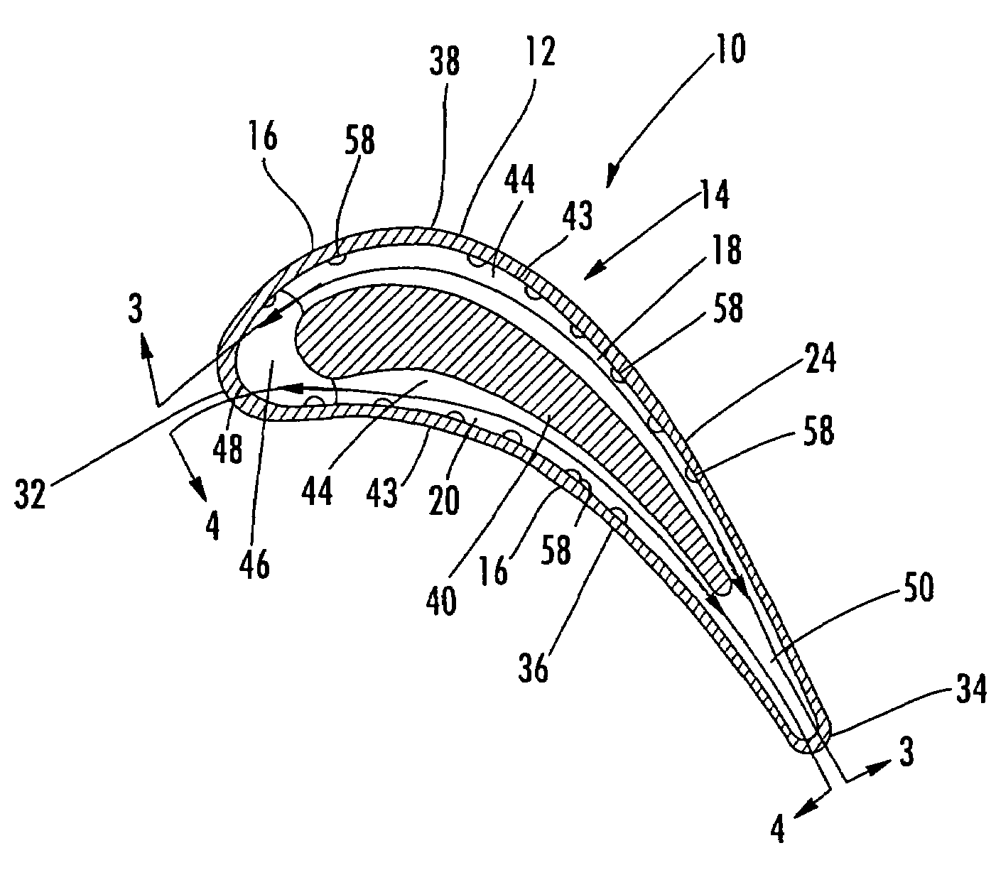
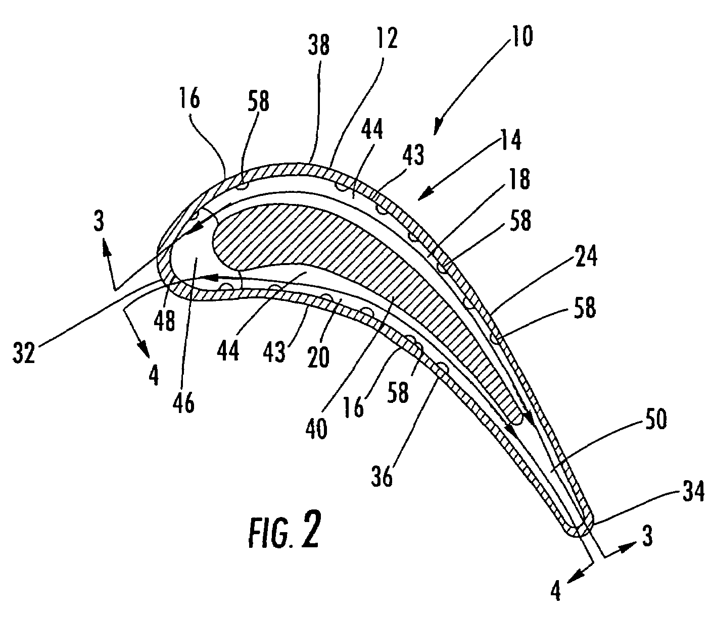
[0025]As shown in FIGS. 1-4, this invention is directed to a turbine airfoil cooling system 10 for a turbine airfoil 12 used in turbine engines. In particular, the turbine airfoil cooling system 10 includes a plurality of internal cavities 14, as shown in FIG. 2, positioned between outer walls 16 of the turbine airfoil 12. The cooling system 10 may include a suction side serpentine cooling channel 18 and a pressure side serpentine cooling channel 20 that each extend along the length of the turbine airfoil 12 with legs 22 that extend in a generally chordwise direction. Such a configuration works well with low cooling fluid flow turbine airfoils.

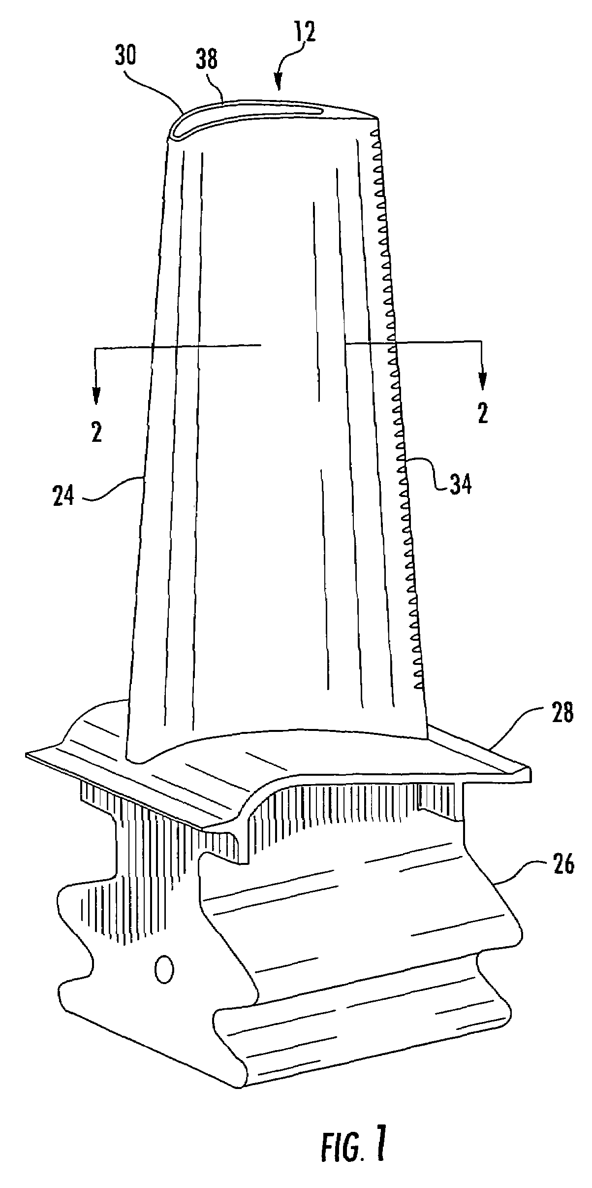
[0026]The turbine airfoil 12 may be formed from a generally elongated, hollow airfoil 24 coupled to a root 26 at a platform 28. The turbine airfoil 12 may be formed from conventional metals or other acceptable materials. The generally elongated airfoil 24 may extend from the root 26 to a tip section 30 and include a leading edge 32 and trailin...


PUM


Abstract

A cooling system for a turbine airfoil of a turbine engine having suction and pressure side serpentine cooling channels formed between an internal support core and an outer wall of the turbine airfoil. The suction and pressure side serpentine cooling channels may be formed from legs extending in a general chordwise direction between leading and trailing edges of the airfoil. The suction and pressure side serpentine cooling channels may receive cooling fluids from a cooling fluid supply source through a cooling fluid inlet, pass the cooling fluids through the cooling system and exhaust the cooling fluids through a cooling fluid exhaust orifice proximate to the tip section. The cooling system is particularly suitable for use with low cooling fluid flow.

Description

FIELD OF THE INVENTION[0001]This invention is directed generally to turbine airfoils, and more particularly to cooling systems in hollow turbine airfoils.BACKGROUND[0002]Typically, gas turbine engines include a compressor for compressing air, a combustor for mixing the compressed air with fuel and igniting the mixture, and a turbine blade assembly for producing power. Combustors often operate at high temperatures that may exceed 2,500 degrees Fahrenheit. Typical turbine combustor configurations expose turbine blade assemblies to these high temperatures. As a result, turbine blades must be made of materials capable of withstanding such high temperatures. In addition, turbine blades often contain cooling systems for prolonging the life of the blades and reducing the likelihood of failure as a result of excessive temperatures.[0003]Typically, turbine blades are formed from a root portion having a platform at one end and an elongated portion forming a blade that extends outwardly from t...

Claims


Application Information

Patent Timeline
Patent Type & Authority Applications(United States)
IPC IPC(8): F01D5/18
CPCF01D5/186F05D2240/127F05D2250/185F01D5/189
Inventor LIANG, GEORGE
Owner SIEMENS ENERGY INC
Why Eureka
Try Eureka