Interpolation image generating method and apparatus

Inactive Publication Date: 2005-07-21
TOSHIBA VISUAL SOLUTIONS CORPORATION
View PDF8 Cites 61 Cited by
  • Summary
  • Abstract
  • Description
  • Claims
  • Application Information

AI Technical Summary

Benefits of technology

[0010] An aspect of the present invention provides an interpolation image generation method of generating an interpolation image between a first reference image of an input video and a second reference image thereof, comprising: dividing each of the first reference image and the second reference image into a plurality of reference regions each including a plurality of pixels, executing a correlation operation between the first reference image and each of at least two first destination images located before and after the first reference image in terms of time and a correlation operation between the second reference image and at least one second destination image corresponding to the second reference image to derive a plurality of

Problems solved by technology

This simply converts a frame rate by displaying the same frame two or three times. However, in the above method, since the number of frames of the video image is insufficient, the movement of the object becomes discontinuity

Method used


Image

  • Interpolation image generating method and apparatus
  • Interpolation image generating method and apparatus
  • Interpolation image generating method and apparatus

Examples


first embodiment

The First Embodiment

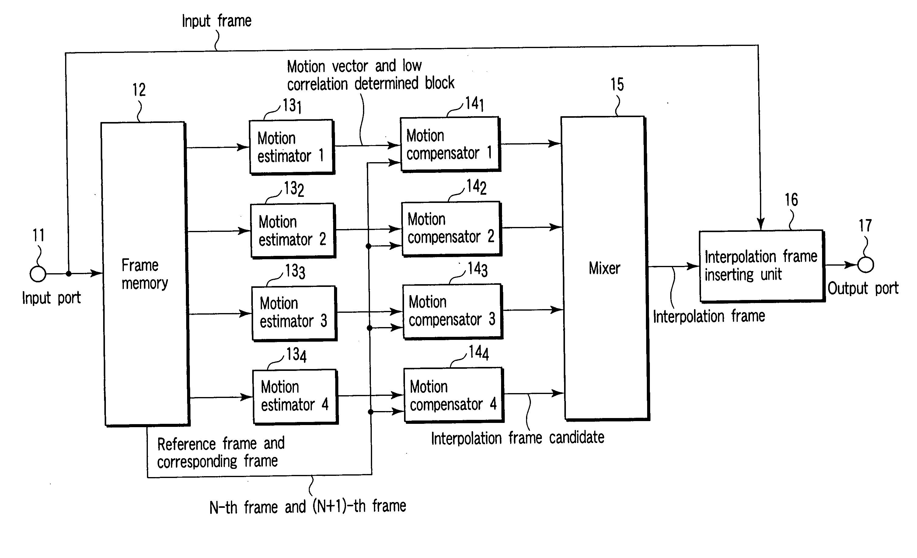
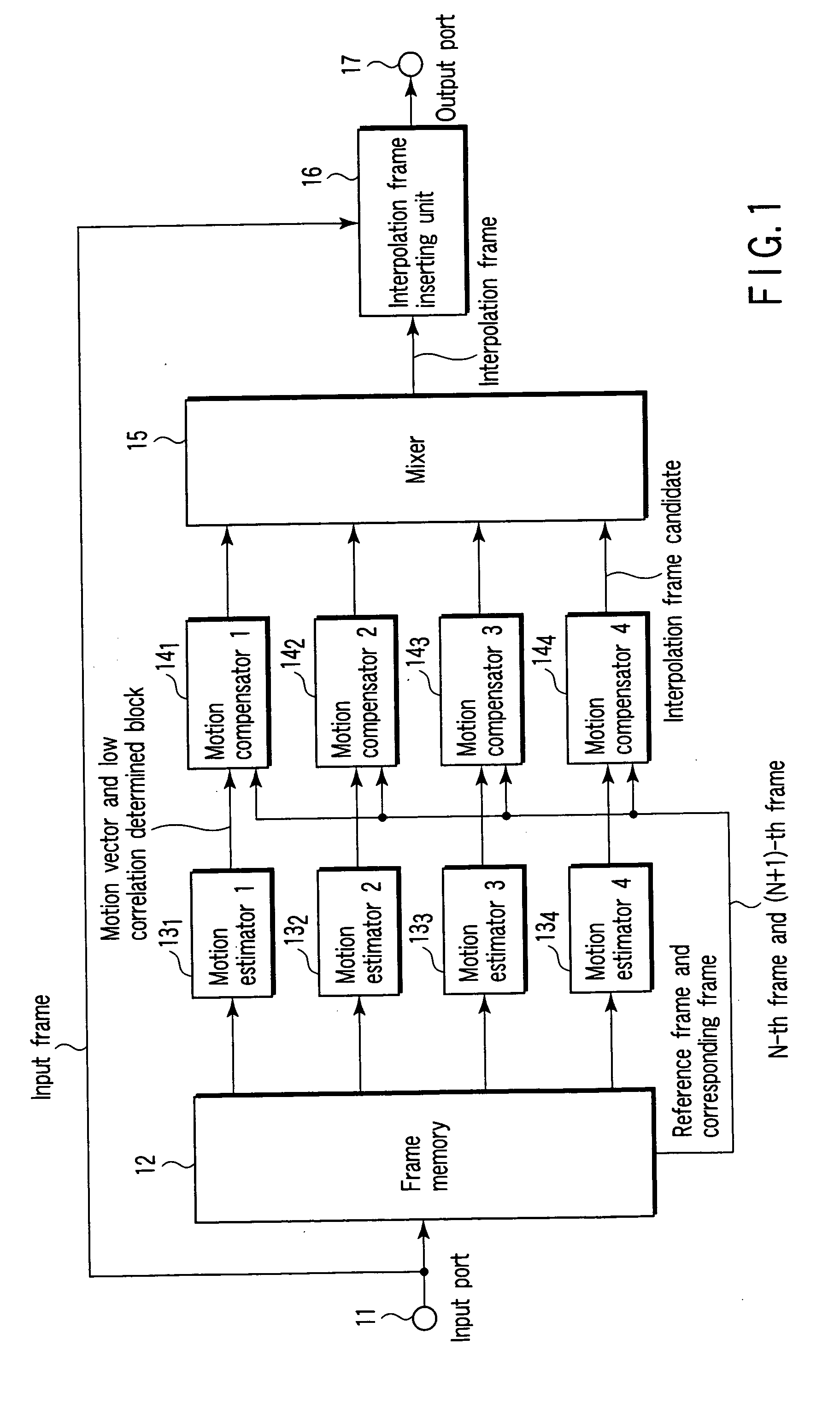
[0030]FIG. 1 shows a block circuit of an interpolation frame generating apparatus implementing an interpolation image generating method according to the first embodiment of the present invention.

[0031] According to this interpolation frame generating apparatus, a frame memory 12 storing a video image input from an input port 11 is connected to input ports of a plurality of motion estimators 13, that is, four motion estimator 131-134. A frame video image from the frame memory 12 is input to the input ports of the motion estimator 131-134. The output ports of the motion estimators 131-134 are connected to the input ports of a plurality of motion compensator 14, that is, four motion compensators 141-144. The output port of the motion compensators 141-144 are connected to a mixer 15. The mixer 15 mixes interpolation frame candidates from the motion compensators 141-144 and outputs an interpolation frame to an interpolation frame inserting unit 16. The interpolation ...


PUM


Abstract

An interpolation image generating method includes dividing each of the first reference image and the second reference image into reference regions each including pixels, executing a correlation operation between the first reference image and first destination images located before and after the first reference image and a correlation operation between the second reference image and a second destination image to derive motion vectors for the first and second destination images every reference region, obtaining correlation values between the regions of the first and second destination images that are indicated by the motion vectors and the reference region to determine the reference region as a high or low correlation region, generating an interpolation image candidate between the first reference and second images using the reference region determined as the high correlation region, and mixing the interpolation image candidates using the motion vectors of the reference region to produce an interpolation image.

Description

CROSS-REFERENCE TO RELATED APPLICATIONS [0001] This application is based upon and claims the benefit of priority from prior Japanese Patent Application No. 2004-008268, filed Jan. 15, 2004, the entire contents of which are incorporated herein by reference. BACKGROUND OF THE INVENTION [0002] 1. Field of the Invention [0003] The present invention relates to an interpolation image generating method of generating an interpolation image between a first reference image and a second reference image and an apparatus therefor. [0004] 2. Description of the Related Art [0005] In recent years, opportunities displaying a video image on various displays such as a cathode ray-tube (CRT), a liquid crystal display (LCD), and an organic electroluminescence display (EL Display) have been increasing. These displays are divided into a hold type display and an impulse type display by a displaying method. In the hold type display such as LCD and EL display, a certain frame of a displayed video image is he...

Claims


Application Information

Patent Timeline
IPC IPC(8): G06T3/40G06T7/20H04N7/01
CPCG06T3/4007H04N7/014G06T7/20
Inventor BABA, MASAHIROMISHIMA, NAO
Owner TOSHIBA VISUAL SOLUTIONS CORPORATION
Why Eureka
Try Eureka