
Method and device for calibrating phase modulation of spatial light modulators by utilizing heterodyne interference

A technology of spatial light modulator and phase modulation, which can be used in measurement devices, instruments, optics, etc., and can solve problems such as large measurement errors

Inactive Publication Date: 2011-06-29
SHENZHEN UNIV
View PDF3 Cites 42 Cited by
  • Summary
  • Abstract
  • Description
  • Claims
  • Application Information

AI Technical Summary

Problems solved by technology

[0004] Traditional methods for detecting the phase modulation characteristics of spatial light modulators include Mach-Zehnder interferometry, double-slit interferometry, circular radial shear interferometry, and Tieman-Green interferometry. These methods have a common feature ——Indirect measurement, that is, the interference fringe pattern is collected by the detector, and the phase information of the spatial light modulator is solved by using the movement of the fringe through image processing. If the fringe contrast of the interferogram is poor and the fringe quality is not ideal, it will be lead to large measurement errors

Method used


Image

  • Method and device for calibrating phase modulation of spatial light modulators by utilizing heterodyne interference
  • Method and device for calibrating phase modulation of spatial light modulators by utilizing heterodyne interference
  • Method and device for calibrating phase modulation of spatial light modulators by utilizing heterodyne interference

Examples


Embodiment Construction

[0022] The implementation of the technical solution will be further described in detail below in conjunction with the accompanying drawings.

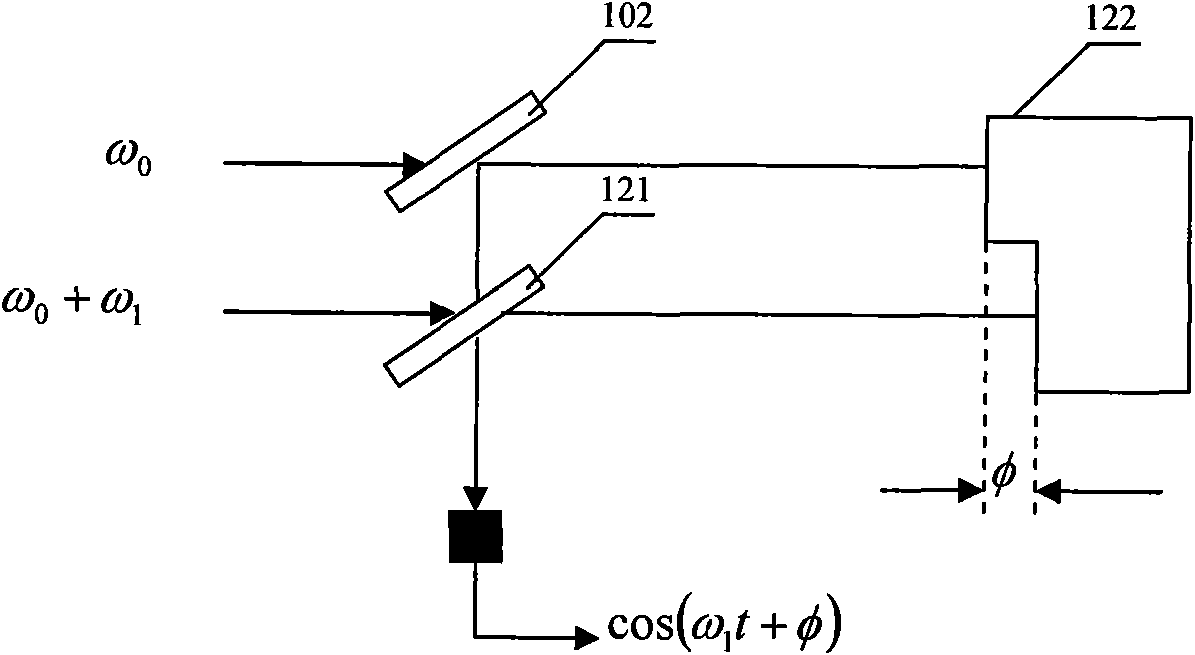
[0023] attached figure 1 It is a schematic diagram of heterodyne interferometric phase detection, in which 102 and 121 are beam splitters, 119 is a photodiode, and 122 is an object to be measured. A beam of frequency ω 0 A beam of light is incident on a certain point on the measurement surface, and a beam frequency is (ω 0 +ω 1 ) beam incident on another point, after reflection the two beams have at least ω 1 Synthesized on a frequency-wide photodetector (usually a photodiode), the detector response is the square of the sum of the complex amplitudes of the light wave. Expressed as:

[0024] i∝[ξ 1 cos ω 0 t+ξ 2 cos((ω 0 +ω 1 )t+φ)] 2 (1)

[0025] where ξ 1 and ξ 2 represent the amplitudes of the two beams of light respectively, omitting the DC component of formula (1), the AC component is simplified as:

[0026] i∝ξ 1 ξ ...


PUM


Abstract

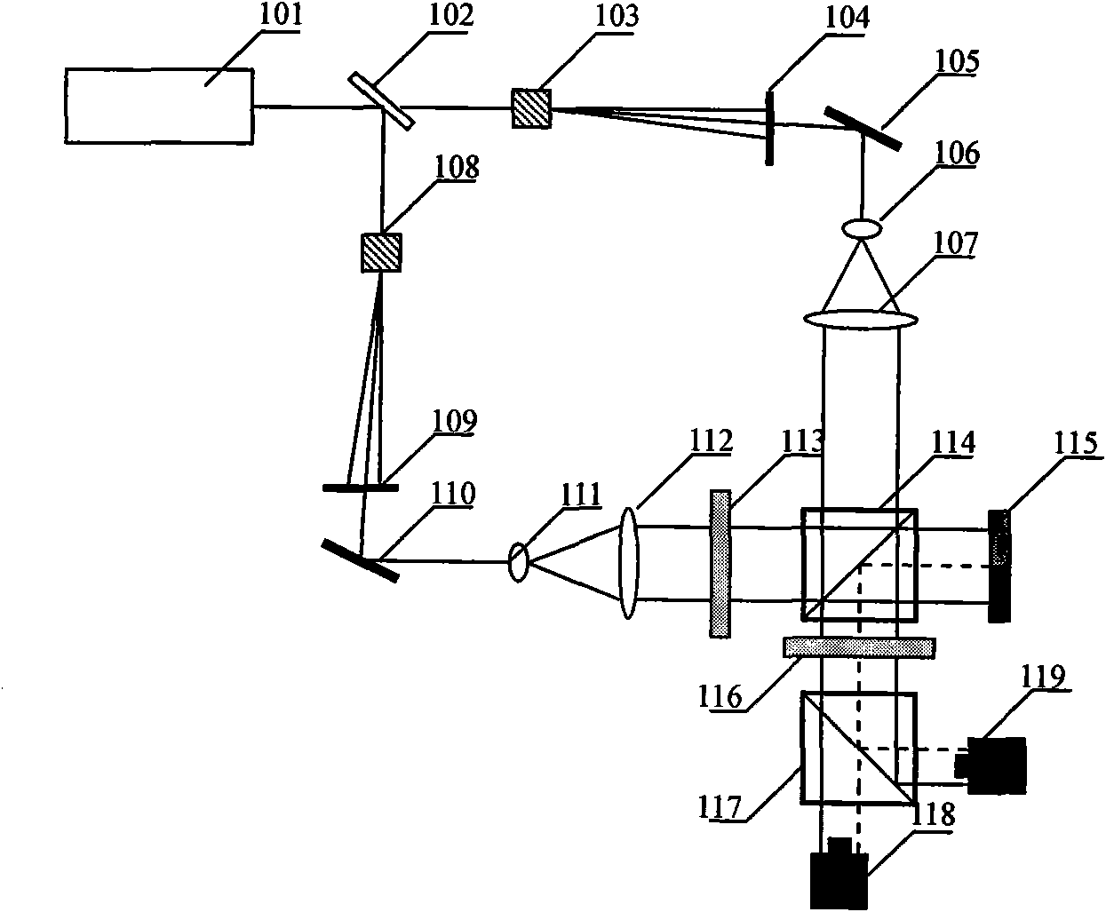
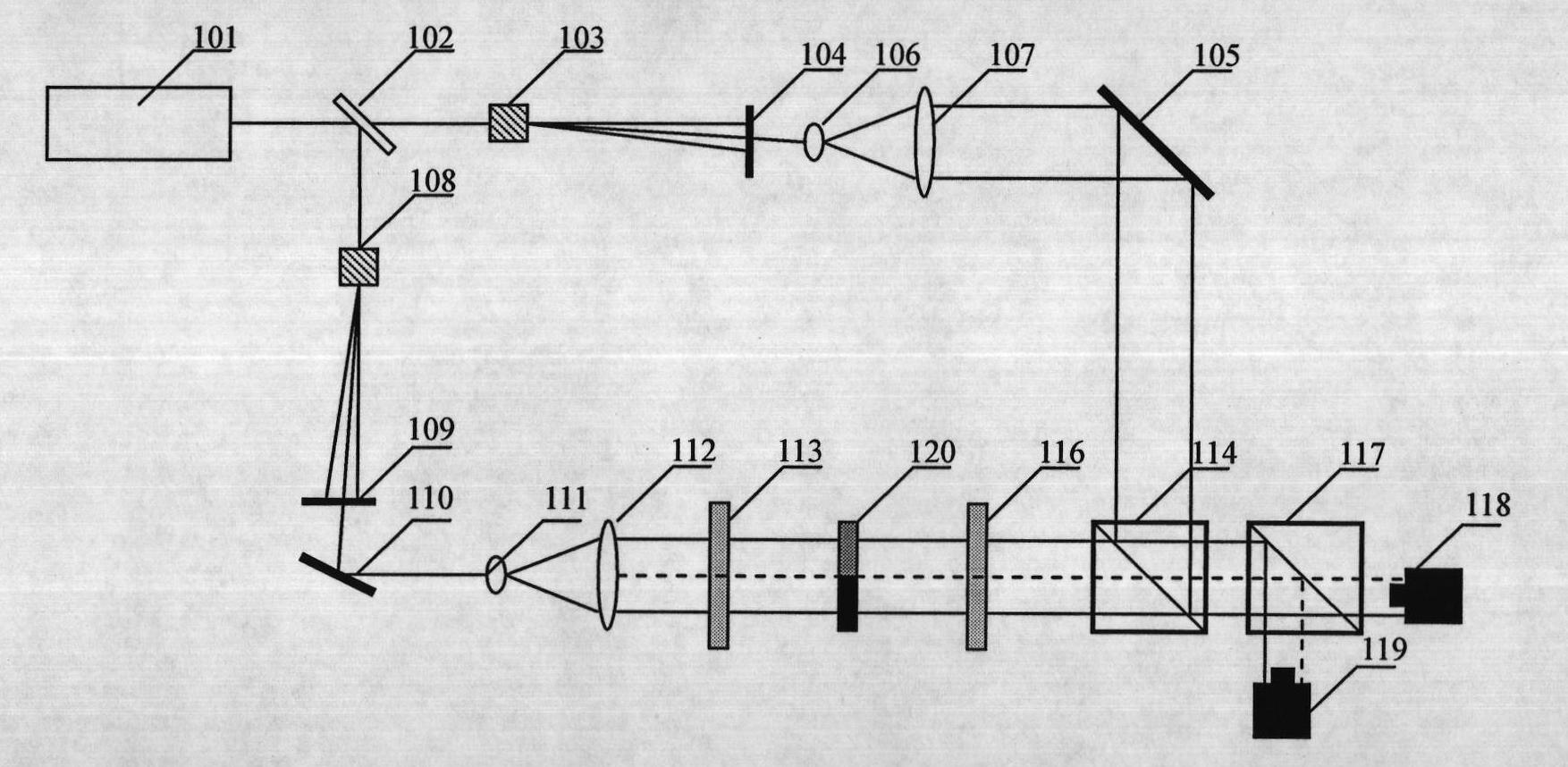
The invention discloses a method for calibrating phase modulation degree of spatial light modulators, and the method is used for detecting the phase modulation information by utilizing a heterodyne interference technology. In the method, two beams of coherent optical waves are led to generate a frequency difference by an acousto-optic frequency phase shifter, and the two beams of coherent optical waves are respectively used as a measuring beam and a reference beam; then the effective display area of the spatial light modulator is divided into two parts, a gray value written into one part is 0, and the part is taken as a reference area; the change range of the gray value of the other part is 0-255, and the other part is taken as a test area; the measuring beam is modulated by the spatial light modulators of the reference area and the test area and then interfered with the reference beam; then two photoelectric detectors at an interference field are utilized to respectively detect a reference signal and a measured signal; and the phase difference between the two photoelectric detectors is the phase modulation degree to be measured, therefore, the corresponding relation between the gray value and the phase modulation degree can be established, so that the phase modulation degree of the spatial light modulators can be calibrated.

Description

technical field [0001] The invention relates to a calibration method for phase modulation of a spatial light modulator, which belongs to the optical information processing technology. Background technique [0002] A Spatial Light Modulator (SLM) is a device capable of spatially modulating part or all of physical quantities such as the amplitude, phase, and polarization state of an input light field according to the requirements of an input control signal. Spatial light modulator has an increasingly important position and value in the field of modern optics. It is an optical and photoelectric hybrid system for optical interconnection, optical correlation, optical calculation, pattern recognition, optical control, optical detection, image processing, The basic building blocks and key devices in the research of display technology and so on. Most of these applications involve the phase modulation characteristics of the device, which is directly related to the effect of the devi...

Claims


Application Information

Patent Timeline
IPC IPC(8): G01M11/02G01J9/02G02B27/10G02F1/11
Inventor 田劲东王瑞松胡名西李东
Owner SHENZHEN UNIV
Learn More