Image forming apparatus and process cartridge

a technology of image forming apparatus and process cartridge, which is applied in the direction of electrographic process apparatus, instruments, developers, etc., can solve the problems of reducing image quality, reducing development performance, and lowering transfer efficiency, so as to improve both transfer efficiency and image quality

Inactive Publication Date: 2005-07-21
RICOH KK
View PDF63 Cites 20 Cited by
  • Summary
  • Abstract
  • Description
  • Claims
  • Application Information

AI Technical Summary

Benefits of technology

[0035] According to the present invention, because the surface friction coefficient of the image carrying unit is less than or equal to 0.3, and the developing unit attaches a developing agent transported by an electrostatic force to the image carrying unit for developing the latent image, the scavenging effect does not happen, and the developing agent adhering to the image portion of the latent does not fall off before transfer even when the surface friction coefficient of the image carrying unit is less than or equal to 0.3; therefore, it is possible able to improve both transfer efficiency and image quality.

Problems solved by technology

When transferring the toner to a piece of paper or an intermediate transferring member, if the toner adheres to the photo-conductor due to a non-electrostatic adhesive force, the toner cannot be transferred by a transfer electric field; as a result, transfer efficiency is lowered and image quality degrades because of insufficient transfer.
When reducing the surface friction coefficient of the image carrier as described in reference 3 and reference 4, however, although the problem of insufficient transfer is solved, the developing performance declines and images of desired density cannot be formed when using the common two-composition contacting developing device or one-composition contacting developing device.
It is thought that this problem is attributed to reduction of the non-electrostatic adhesive force imposed on the toner on the image carrier, which counteracts magnetic particle chains occurring in development or a mechanical scavenging effect (scraping effect) in a developing sleeve, and thus the toner falls off easily.
As a result, by just reducing the surface friction coefficient of the image carrier, although transfer efficiency is improved, image quality degrades.
When the developing device employing the aforesaid toner cloud is used, the same problem occurs in that the toner adhering to the image carrier falls off easily.
Hence, similarly, by just reducing the surface friction coefficient of the image carrier, although transfer efficiency is improved, image quality degrades.
When the developing device using the aforesaid AC bias is used, although the mechanical scavenging effect does not occur, the so-called electrical scavenging effect occurs; similarly, by just reducing the surface friction coefficient of the image carrier, although transfer efficiency is improved, image quality degrades.
However, because the AC bias is applied at the same time, the toner is also attached to the non-image portion of the latent image, which is not to be developed into an image, hence, the non-image portion is stained with the toner, that is, so-called scumming occurs.
Further, because of the scavenging effect, even when the surface friction coefficient of the image carrier is reduced, in practice, it is difficult to reduce the surface friction coefficient uniformly, and the surface friction coefficient changes with time.
Especially, when the surface friction coefficient is less than 0.2, stripe-like unevenness occurs in the obtained image because of the non-uniform developing ability.
Therefore, transfer efficiency and cleaning efficiency cannot be improved sufficiently.
However, because the adhesive force between the spherical toner and the image carrier is even weaker, if the surface friction coefficient of the image carrier is reduced when the aforesaid toner cloud developing device or AC bias developing device is used, insufficient transfer occurs more easily.

Method used


Image

  • Image forming apparatus and process cartridge
  • Image forming apparatus and process cartridge
  • Image forming apparatus and process cartridge

Examples


Embodiment Construction

[0059] Below, preferred embodiments of the present invention are explained with reference to the accompanying drawings.

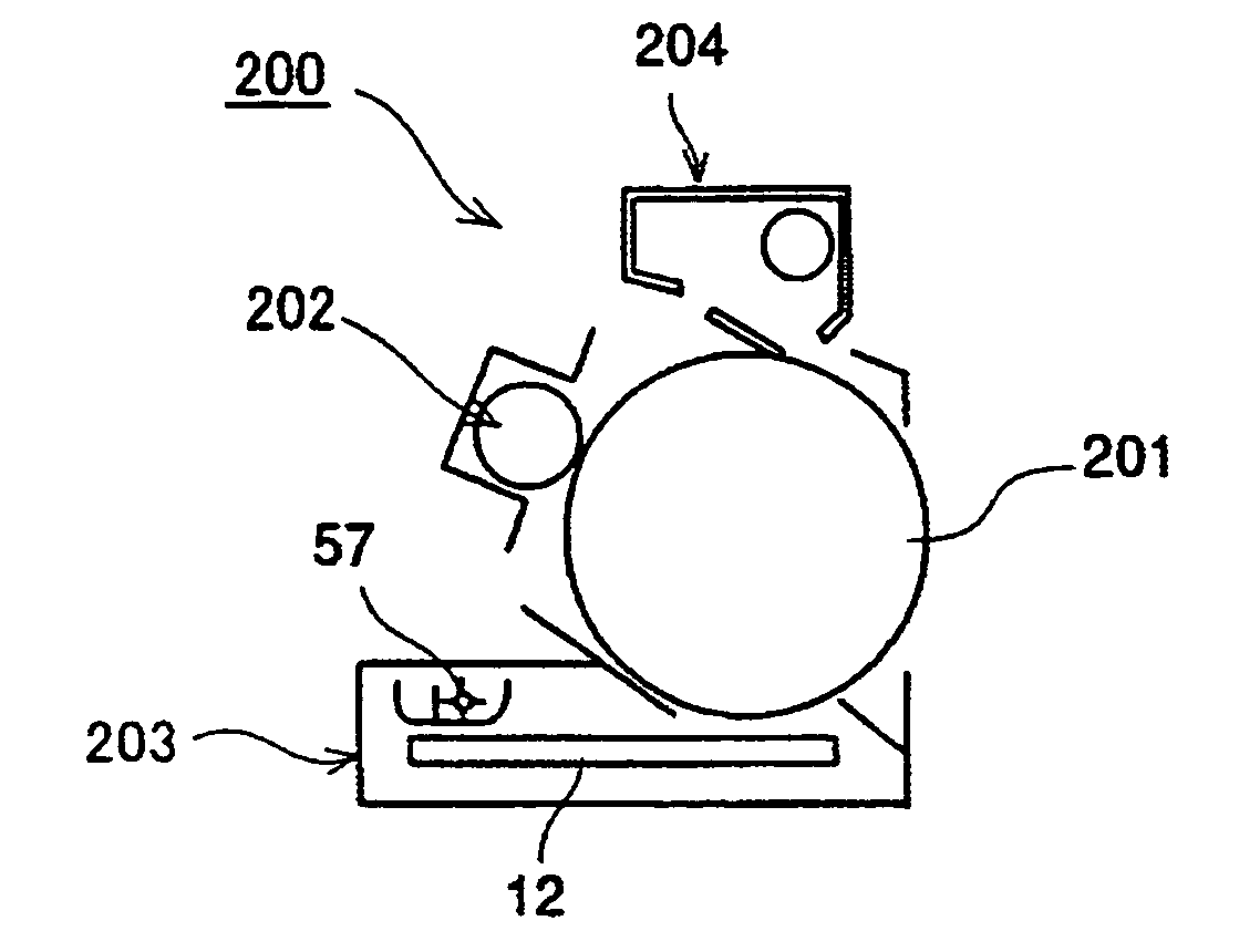
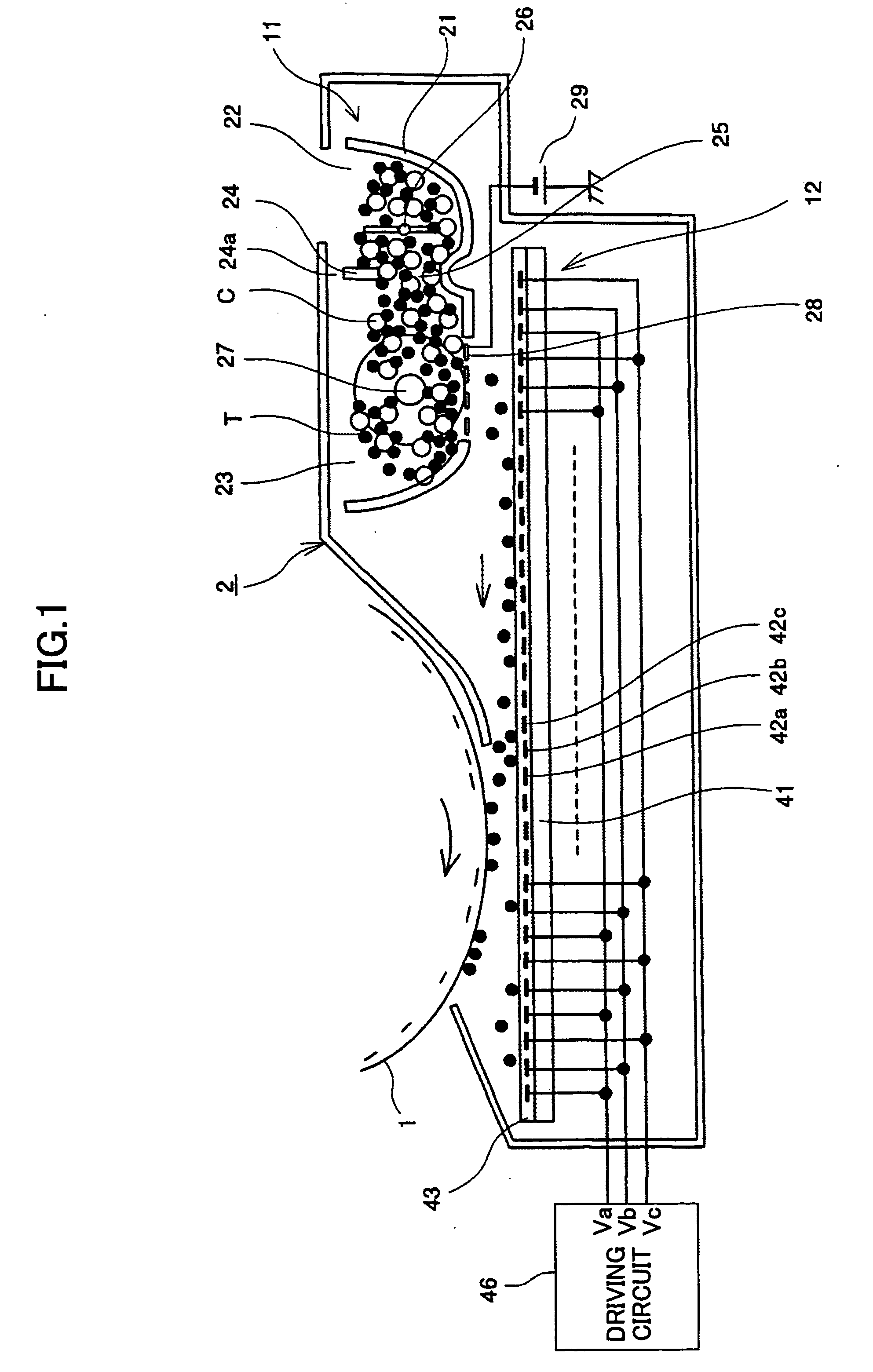
[0060]FIG. 1 is a view schematically showing a configuration of a developing portion of an image forming apparatus according to an embodiment of the present invention.

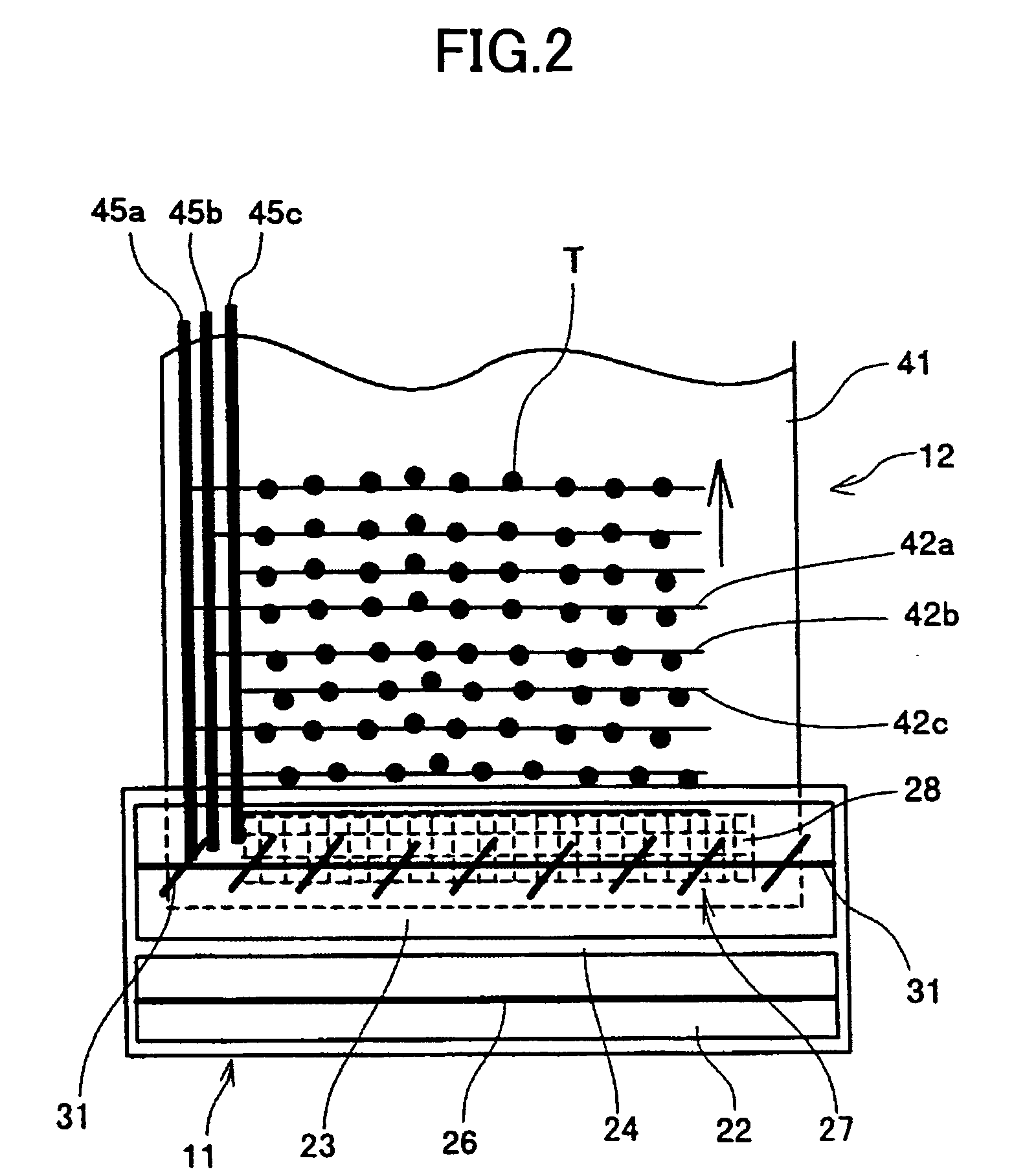
[0061]FIG. 2 is a plan view schematically showing the configuration of the developing portion of the image forming apparatus as illustrated in FIG. 1.

[0062] The image forming apparatus includes an image carrier 1 including an organic photo-conductor with latent images formed thereon, and an electrostatic developing device 2 which develops the latent images on the image carrier 1 by using a two-composition developing agent including a toner T and a carrier C while transporting the toner T by a traveling wave electric field. That is, here, the developing device 2 is exemplified to be an electrostatic developing device. In FIG. 1, it is illustrated that the image carrier 1 is in a form of a drum, but t...


PUM


Abstract

An image forming apparatus is disclosed that is able to improve transfer efficiency and image quality. The image forming apparatus includes an organic photo-conductor with latent images formed thereon, and a developing unit for developing the latent images. The organic photo-conductor has surface friction coefficient less than or equal to 0.3. The developing unit develops the latent images while transporting a two-composition developing agent including a toner T and a carrier C by a traveling wave electric field.

Description

BACKGROUND OF THE INVENTION [0001] 1. Field of the Invention [0002] The present invention relates to an image forming apparatus and a process cartridge. [0003] 2. Description of the Related Art [0004] In an image forming apparatus, such as a printer, a copier, or a fax machine, an electrophotographic process is used to form latent images on an image carrier, a developing agent powder (referred to as a “toner” below) is attached to the latent images to develop the latent images into visible toner images. These toner images are transferred to a recording medium (including intermediate transferring members), and target images are formed. [0005]FIG. 19 illustrates an example of a developing device for attaching the toner to the electrostatic latent images formed on the image carrier in the aforementioned image forming apparatus. As illustrated in FIG. 19, a developing roller 1002, to which a DC bias voltage is applied by a developing bias power supply 1003, is controlled to rotate at a ...

Claims


Application Information

Patent Timeline
Patent Type & Authority Applications(United States)
IPC IPC(8): G03G9/08G03G5/047G03G5/05G03G5/147G03G9/087G03G15/00G03G15/08G03G21/00G03G21/18
CPCG03G15/75G03G15/0803
Inventor NAKAZATO, YASUSHIHORIKE, MASANORIMIYAGUCHI, YOHICHIROHKONDOH, NOBUAKISAKAI, KATSUO
Owner RICOH KK
Why Eureka
Try Eureka