Distortion reduction calibration

a calibration circuit and reduction technology, applied in the direction of receiver monitoring, transmission monitoring, instruments, etc., can solve the problems of increasing interference between wireless communication systems, interference with desired signals, and possible interference, so as to reduce the second order nonlinear response of the receiver output signal.

Active Publication Date: 2005-07-21
QUALCOMM INC
View PDF40 Cites 25 Cited by
  • Summary
  • Abstract
  • Description
  • Claims
  • Application Information

AI Technical Summary

Benefits of technology

[0020] In one embodiment, the circuit is for use in a factor calibration wherein the receiver generates a down-converted output signal and is configured to receive an external input signal to permit the adjustment of the gain stage to thereby minimize the second order nonlinear response of the receiver output signal.

Problems solved by technology

Due to this crowding, increased interference between wireless communication systems is commonplace.
In this situation, interference may be likely.
One example of such interference occurs in a code division multiple access (CDMA) wireless system.
However, the difference signal, designated herein as ΔωJ, may well be inside the desired channel and thus cause significant interference with the desired signal.
In this circumstance, the AMPS signals are considered a jammer signals since they create interference and therefore jam the desirable CDMA signal.
If this second-order distortion signal is inside the channel bandwidth, the jammer rejection filters 28 and 30 will be ineffective and the resultant interference may cause an unacceptable loss of carrier-to-noise ratio.
Only the frequency separation is important if the second-order distortion results in the introduction of an undesirable signal into the channel bandwidth of the CDMA unit.
It should be noted that the second-order distortion discussed herein is a more serious problem using the direct down-conversion architecture illustrated in FIG. 1.
Therefore, the IIP2 specification for a super-heterodyne receiver is generally not difficult to achieve.
The IIP2 requirement is often the single most difficult parameter to achieve in a direct down-conversion receiver architecture.
Thus, the individual circuit components and unique combination of circuit components selected for a particular wireless communication device results in unpredictability in the IIP2 value for any given unit.

Method used


Image

  • Distortion reduction calibration
  • Distortion reduction calibration
  • Distortion reduction calibration

Examples


Embodiment Construction

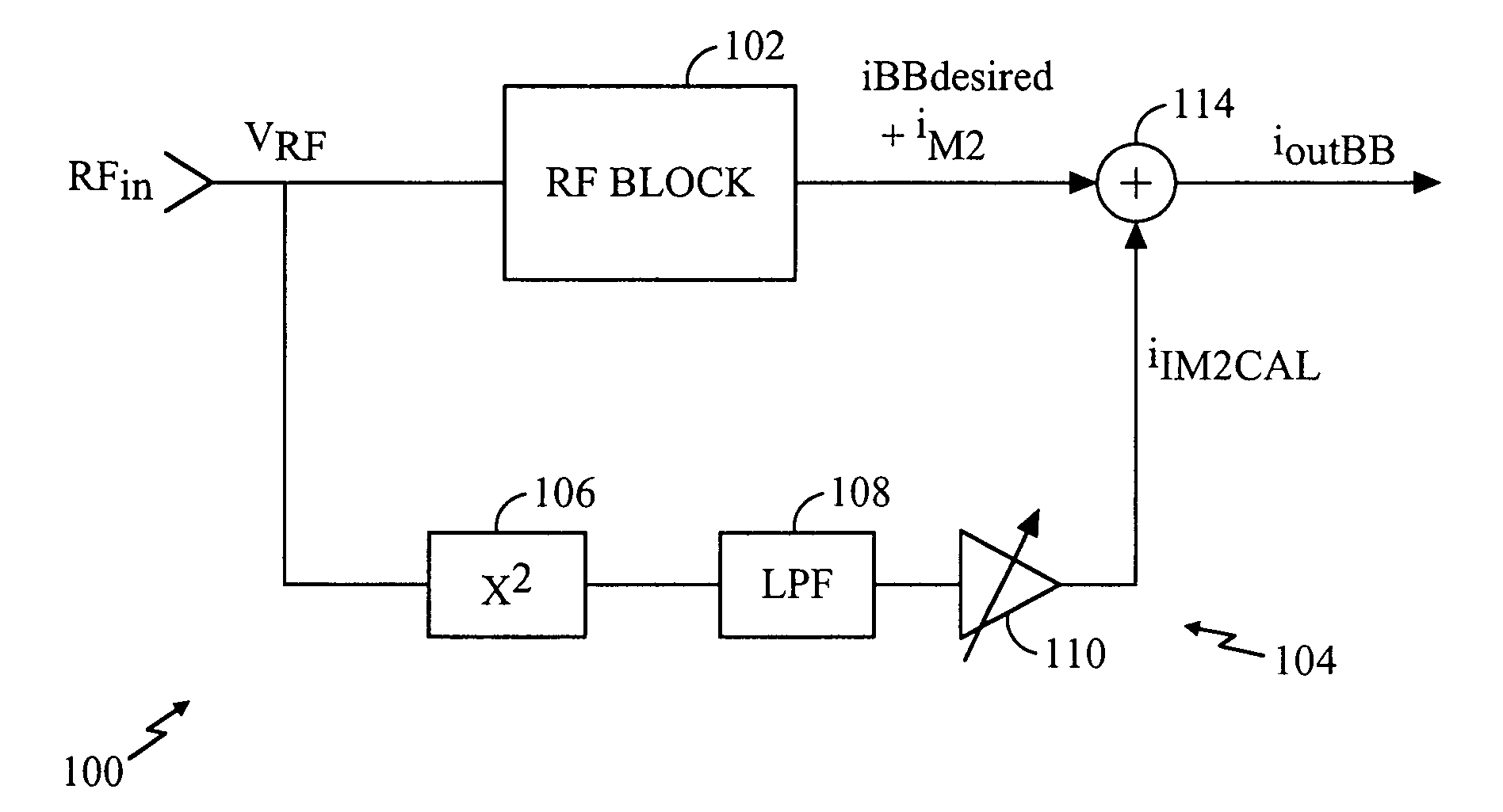
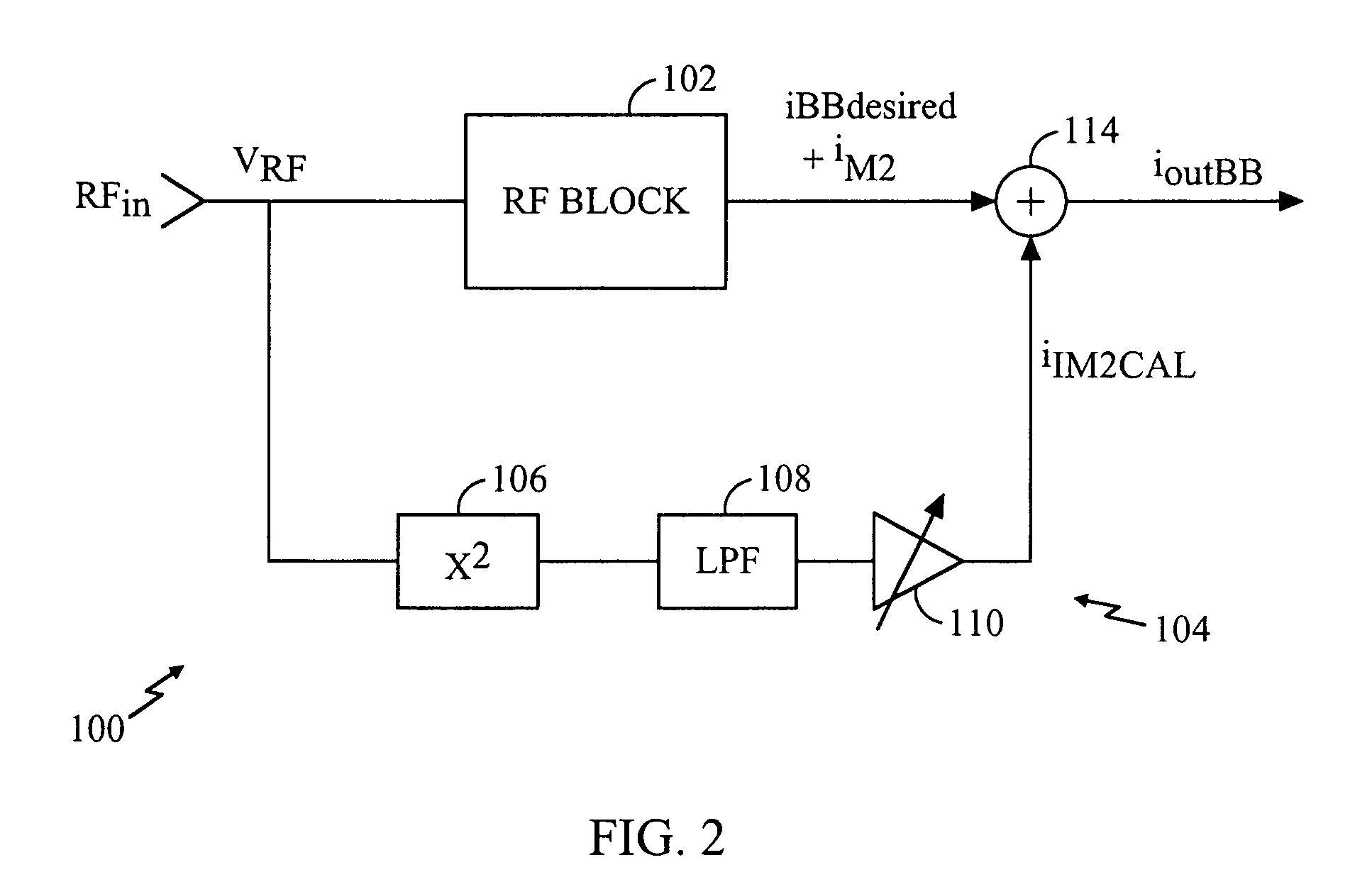
[0030] The present invention is directed to a calibration circuit and method that simplifies the calibration process for individual wireless communication devices. The term “wireless communication device” includes, but is not limited to, cellular telephones, personal communication system (PCS) devices, radio telephones, mobile units, base stations, satellite receivers and the like. In one embodiment, the calibration circuit is used at assembly to compensate for variations in components. In an alternative embodiment, also described herein, an onboard calibration circuit can be used to compensate for component mismatch due to circuit aging or other changes in circuit operational parameters.

[0031] IIP2 performance presents a major challenge in direct conversion down-converters. The required values of IIP2 are usually very high and the actual performance tends to be difficult to predict because it is almost exclusively determined by statistical phenomena. That is, component mismatch te...


PUM


Abstract

Techniques are disclosed for compensating for second-order distortion in a wireless communication device. In a zero-intermediate frequency (IF) or low-IF architecture, IM2 distortion generated by the mixer (20) results in undesirable distortion levels in the baseband output signal. A compensation circuit (104) provides a measure of the IM2 distortion current independent of the radio frequency (RF) pathway to generate an IM2 calibration current. The IM2 calibration current is combined with the baseband output signal to thereby eliminate the IM2 currents generated within the RF pathway. In one embodiment, the calibration is provided at the factory during final testing. In alternative embodiment, additional circuitry (156, 158) may be added to the wireless communication device to provide a pathway between the transmitter (150) and the receiver (146). The transmitter signal is provided to the receiver to permit automatic calibration of the unit. An internal signal source (162) may be used in place of the transmitter (150). The auto-calibration may be performed to eliminate IM2 distortion or permit optimization of the circuit to minimize other forms of distortion or interference.

Description

CROSS REFERENCE TO RELATED APPLICATIONS [0001] This application is a divisional of U.S. patent application Ser. No. 10 / 066,115, filed Feb. 2, 2002, entitled “DISTORTION REDUCTION CALIBRATION”.BACKGROUND [0002] 1. Field of the Invention [0003] The present invention is related generally to wireless communication devices, and, more particularly, to a system and method for a distortion reduction calibration circuit in a wireless communication device. [0004] 2. Description of the Related Art [0005] Wireless communication systems are proliferating as more and more service providers add additional features and technical capabilities. A large number of service providers now occupy a relatively limited portion of the radio frequency spectrum. Due to this crowding, increased interference between wireless communication systems is commonplace. For example, wireless communication systems from two different service providers may occupy adjacent portions of the spectrum. In this situation, interfe...

Claims


Application Information

Patent Timeline
Patent Type & Authority Applications(United States)
IPC IPC(8): H04B1/12H04B1/30H04B17/00
CPCH04B1/12H04B17/20H04B17/10H04B1/30H04B1/10
Inventor SHAH, PETER JIVAN
Owner QUALCOMM INC
Why Eureka
Try Eureka