
Method and apparatus for audio compression

a compression method and audio technology, applied in the field of data compression, can solve the problems of large amount of quantization errors, relatively poor quality synthesized (decompressed) audio signals, and typically not taking into account relatively substantial components of audio signals

Inactive Publication Date: 2005-07-21
XVD TECH HLDG LTD IRELAND
View PDF23 Cites 33 Cited by
  • Summary
  • Abstract
  • Description
  • Claims
  • Application Information

AI Technical Summary

Problems solved by technology

Unfortunately, such techniques typically do not take into account relatively substantial components of an audio signal.
Thus, such techniques result in a relatively poor quality synthesized (decompressed) audio signal due to loss of information.
However, transform frequency coefficient quantization errors are spread over the entire length of a frame.
However, a sound attack may only occupy part of an entire signal bandwidth.
Large transform length also leads to large computational complexity.
Furthermore, the amplitude transfer function of conventional MDCT is not “flat” enough.
These irregularities make it difficult to use MDCT coefficients for psycho-acoustic analysis of the audio signal and to compute bit allocation.
Conventional audio codecs compute auxiliary spectrum (typically with FFT, which is computationally expensive) for constructing a psycho-acoustic model (PAM).

Method used


Image

  • Method and apparatus for audio compression
  • Method and apparatus for audio compression
  • Method and apparatus for audio compression

Examples


Embodiment Construction

[0024] In the following description, numerous specific details are set forth to provide a thorough understanding of the invention. However, it is understood that the invention may be practiced without these specific details. In other instances, well-known circuits, structures, standards, and techniques have not been shown in detail in order not to obscure the invention.

Overview

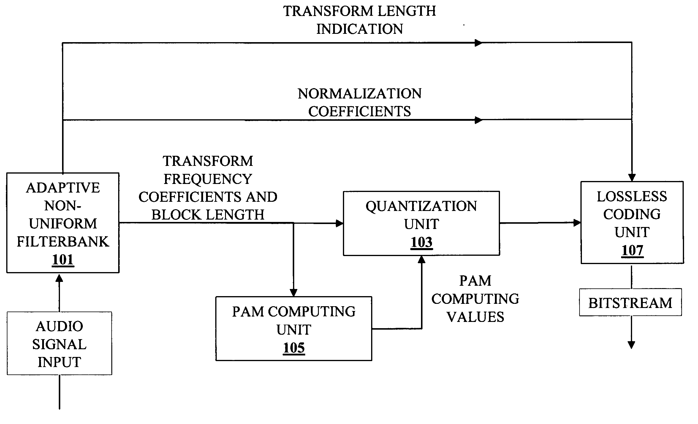
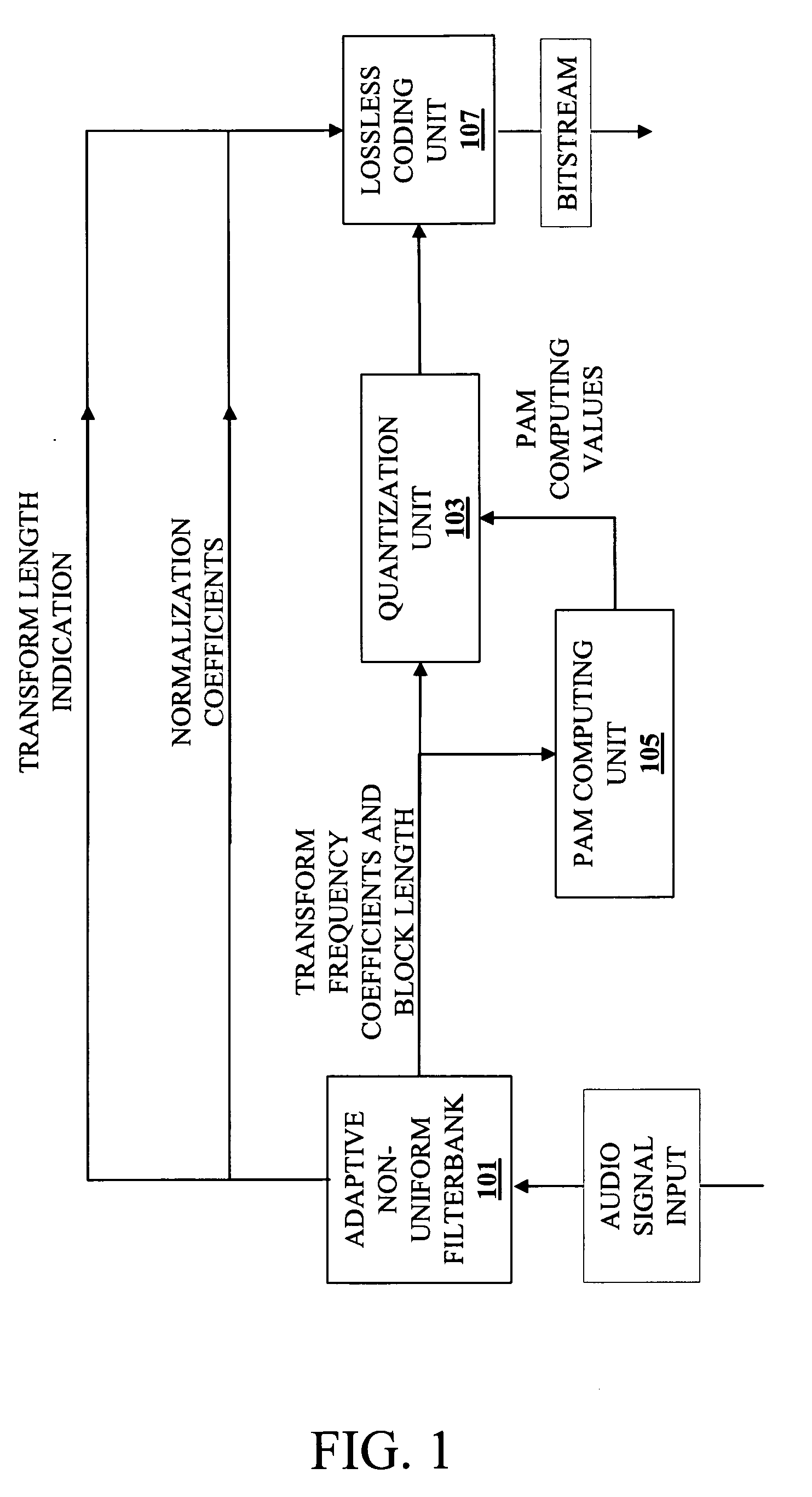
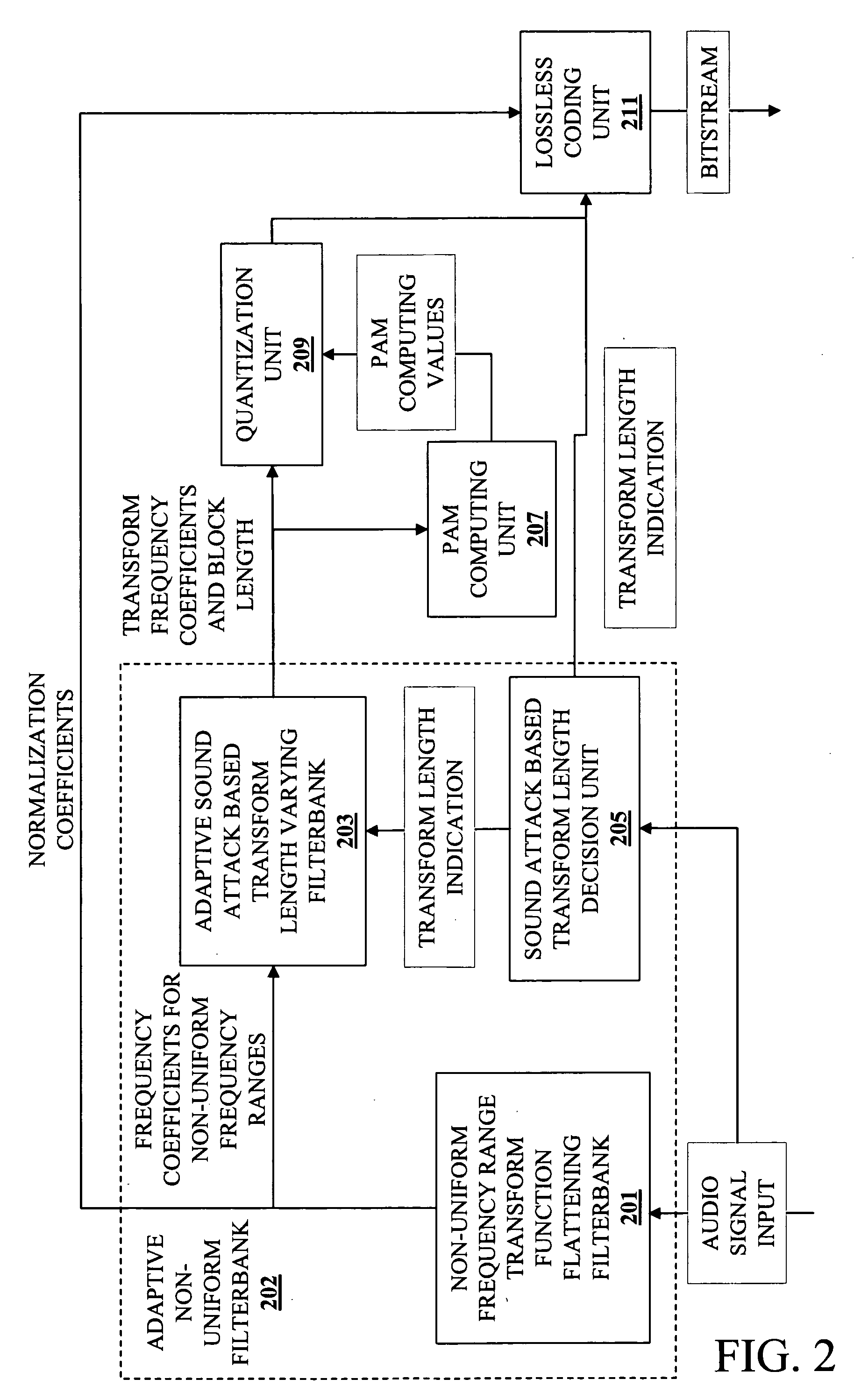
[0025] A method and apparatus for audio compression is described. According to one embodiment of the invention, a method and apparatus for audio compression generates frequency ranges of non-uniform width (i.e., the frequency ranges are not all represented by the same number of transform frequency coefficients) during encoding of an audio input signal. Each of these non-uniform frequency ranges is processed separately, thus reducing the computational complexity of processing the audio signal represented by the frequency ranges. Partitioning (logical or actual) a transformed audio signal input into non-unifo...


PUM


Abstract

A method and apparatus for audio compression receives an audio signal. Transform coding is applied to the audio signal to generate a sequence of transform frequency coefficients. The sequence of transform frequency coefficients is partitioned into a plurality of non-uniform width frequency ranges and then zero value frequency coefficients are inserted at the boundaries of the non-uniform width frequency ranges. As a result, certain of the transform frequency coefficients that represent high frequencies are dropped.

Description

CROSS REFERENCE TO RELATED APPLICATIONS [0001] This is a divisional application of U.S. patent application Ser. No. 10 / 378,455, filed Mar. 3, 2003, which claims priority from U.S. Provisional Patent Application Ser. No. 60 / 450,943, filed Feb. 28, 2003.BACKGROUND OF THE INVENTION [0002] 1. Field of the Invention [0003] The invention relates to the field of data compression. More specifically, the invention relates to audio compression. [0004] 2. Background of the Invention [0005] To allow typical computing systems to process (e.g., store, transmit, etc.) audio signals, various techniques have been developed to reduce (compress) the amount of data representing an audio signal. In typical audio compression systems, the following steps are generally performed: (1) a segment or frame of an audio signal is transformed into a frequency domain; (2) transform coefficients representing (at least a portion of) the frequency domain are quantized into discrete values; and (3) the quantized value...

Claims


Application Information

Patent Timeline
Patent Type & Authority Applications(United States)
IPC IPC(8): G10L19/02G10L19/14G10L21/04H04BH04B1/66
CPCG10L19/02
Inventor KOLESNIK, VICTOR D.KUDRYASHOV, BORIS D.PETROV, SERGEYOVSYANNIKOV, EVGENYTROJANOVSKY, BORISTROFIMOV, ANDREY
Owner XVD TECH HLDG LTD IRELAND
Learn More