

Vehicle steering wheel
a steering wheel and vehicle technology, applied in the direction of vehicle steering controls, basic electric elements, electrical equipment, etc., can solve the problems of complex installation and high manufacturing cost, and achieve the effect of low overall heigh
- Summary
- Abstract
- Description
- Claims
- Application Information
AI Technical Summary
Benefits of technology
Problems solved by technology
Method used
Image

Examples
Embodiment Construction
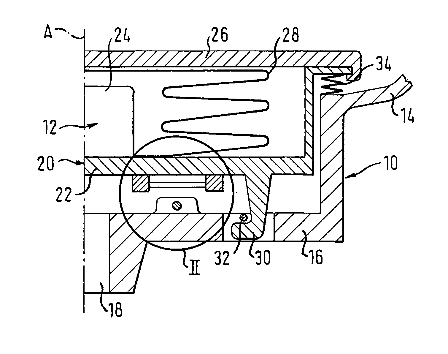
[0017] According to FIG. 1, a vehicle steering wheel has a steering wheel skeleton 10 and a gas bag module 12. The longitudinal axis A of the steering wheel is represented by a dot-and-dash line. The steering wheel skeleton 10 has a steering wheel rim, surrounded by foam, not illustrated, which is connected by means of spokes 14 with a cup-shaped steering wheel hub 16. In the region of the longitudinal axis A of the vehicle steering wheel, the hub 16 has a mounting opening 18 to receive a steering column.
[0018] The gas bag module 12, constructed as a “floating horn” is illustrated by way of example and has a cup-shaped module housing 20 with a base 22, which at the same time forms the carrier for a gas generator 24. The module housing 20 is closed towards the vehicle interior with a covering 26, which covers a gas bag 28 folded inside the module housing 22.
[0019] On the underside of the base 22, several detent hooks 30, constructed in a known manner, are formed for fastening the m...
PUM
 Abstract
Description
Claims
Application Information