Modified high efficiency kinetic spray nozzle

a high-efficiency, kinetic spray nozzle technology, applied in plasma technique, combustion types, lighting and heating apparatus, etc., can solve the problems of limiting the main gas temperature that can be used, affecting the performance and affecting the efficiency of the kinetic spray nozzl

Active Publication Date: 2005-07-28
FLAME SPRAY IND
View PDF94 Cites 39 Cited by
  • Summary
  • Abstract
  • Description
  • Claims
  • Application Information

AI Technical Summary

Benefits of technology

[0007] In another embodiment, the present invention is a kinetic spray system comprising: a supersonic nozzle having a converging region and a diverging region separated by a throat; at least a portion of the diverging region adjacent the throat having a cross-sectional expansion rate of at least 1.0 millimeters squared per millimeter; at least one powder injector connected to the nozzle with one of a low pressure or a high pressure powder feeder connected to said injector; and a high pressure source of a heated main gas connected to the nozzle.

Problems solved by technology

These powder feeders are very expensive and can cause erosion of the throat of the kinetic spray nozzle.
In addition, high pressure systems are prone to clogging at the throat of the nozzle, which limits the main gas temperatures that can be used.
One problem encountered with both low pressure and high pressure nozzles is the inability of certain types of particles to achieve critical velocity even at higher main gas temperatures and pressures.

Method used


Image

  • Modified high efficiency kinetic spray nozzle
  • Modified high efficiency kinetic spray nozzle
  • Modified high efficiency kinetic spray nozzle

Examples


Embodiment Construction

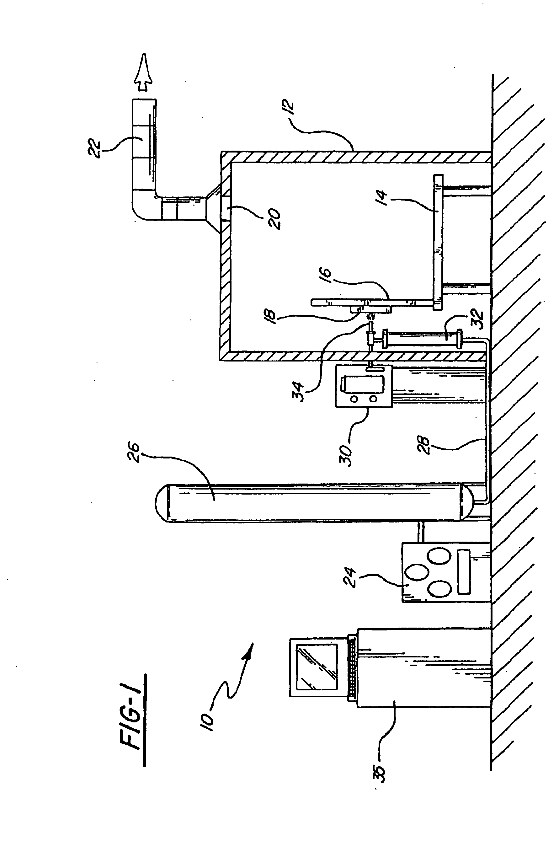
[0017] Referring first to FIG. 1, a kinetic spray system according to the present invention is generally shown at 10. System 10 includes an enclosure 12 in which a support table 14 or other support means is located. A mounting panel 16 fixed to the table 14 supports a work holder 18 capable of movement in three dimensions and able to support a suitable workpiece formed of a substrate to be coated. The work holder 18 is preferably designed to move a substrate relative to a nozzle 34 of the system 10, thereby controlling where the powder material is deposited on the substrate. In other embodiments the work holder 18 is capable of feeding a substrate past the nozzle 34 at traverse rates of up to 50 inches per second. The enclosure 12 includes surrounding walls having at least one air inlet, not shown, and an air outlet 20 connected by a suitable exhaust conduit 22 to a dust collector, not shown. During coating operations, the dust collector continually draws air from the enclosure 12 a...


PUM

PropertyMeasurementUnit
lengthaaaaaaaaaa
diameteraaaaaaaaaa
velocityaaaaaaaaaa

Abstract

A modified high efficiency kinetic spray nozzle is disclosed. The modified nozzle has a rapid expansion rate in the diverging region relative to prior art nozzles, which enables one to achieve much higher particle velocities without an increase in the main gas temperature. Preferably, the expansion rate of the supersonic nozzle in a portion of the diverging region is at least 1 mm2 per millimeter, more preferably 2 mm2 per millimeter, more preferably 5 mm2 per mm, with a most preferable expansion rate being 10 mm2 per millimeter.

Description

INCORPORATION BY REFERENCE [0001] The present invention comprises an improvement to the kinetic spray process as generally described in U.S. Pat. Nos. 6,139,913, 6,283,386 and the articles by Van Steenkiste, et al. entitled “Kinetic Spray Coatings” published in Surface and Coatings Technology Volume III, Pages 62-72, Jan. 10, 1999, and “Aluminum coatings via kinetic spray with relatively large powder particles”, published in Surface and Coatings Technology 154, pp. 237-252, 2002, all of which are herein incorporated by reference.TECHNICAL FIELD [0002] The present invention is directed toward a design for a supersonic nozzle, and more particularly, toward a nozzle for a kinetic spray system. BACKGROUND OF THE INVENTION [0003] A new technique for producing coatings on a wide variety of substrate surfaces by kinetic spray, or cold gas dynamic spray, was recently reported in two articles by T. H. Van Steenkiste et al. The first was entitled “Kinetic Spray Coatings,” published in Surface...

Claims


Application Information

Patent Timeline
Patent Type & Authority Applications(United States)
IPC IPC(8): B05B7/14C23C24/04
CPCC23C24/04B05B7/1486
Inventor STEENKISTE, THOMAS HUBERT VANHAN, TAEYOUNGGILLISPIE, BRYAN A.
Owner FLAME SPRAY IND
Why Eureka
Try Eureka