Antenna apparatus

Inactive Publication Date: 2005-07-28
SONY CORP
View PDF7 Cites 35 Cited by
  • Summary
  • Abstract
  • Description
  • Claims
  • Application Information

AI Technical Summary

Benefits of technology

[0021] Thus, according to the present invention, a formation of more than one antenna circuit ensures that a multi-frequency antenna being adaptive to more than one frequency and besides, capable of controlling the directivity pattern is realizable. Further, in this case, the second antenna elements may be used in common as the first antenna circuit and the second antenna circuit, so that the downsizing of the antenna apparatus is attainable.

Problems solved by technology

However, the antenna apparatus of the above patent document 1 is in the form of an array of multiple Yagi-Uda antennas, and thus requires more than one director and more than one reflector, resulting in a disadvantage of being difficult of a downsizing.
Further, the antenna apparatus of the above patent document 1 is supposed to be of a structure in which a monopole antenna is projecting in a vertical direction of a ground plate, also resulting in a difficulty in attaining a reduction in thickness.
Alternatively, it is also suggested that a dipole antenna should be used in place of the monopole antenna, for instance, to form the antenna on a printed circuit board, in which case, however, the ground plate fails to be disposed in the vicinity of the antenna, resulting in a difficult packaging of a selector switch etc.
Further, the monopole antenna, even if formed with a dielectric substance, has little effect of shortening a wavelength, resulting in a disadvantage of being difficult of the downsizing.
Further, the antenna apparatus of the above configuration needs a selector switch between transmitting and receiving systems for each beam direction to attain the formation of multi-beams, resulting in a disadvantage in that the selector switch leads to a degradation of efficiency as the antenna.
Furthermore, the antenna apparatus of the above configuration is basically supposed to have one transmitting / receiving system, so that a one-to-multiple switching is required for the selector switch, resulting in a disadvantage of being very difficult of a manufacturing adaptive to an available frequency band of a radio communication.
Moreover, the antenna apparatus of each of the above patent documents 1 and 2 has been considered to be incapable of using a transmitting / receiving frequency at more than one frequency.
On the contrary, the multi-frequency sharable multi-beam antenna of the above patent document 3 is supposed to be available at more than one frequency, in which case, however, the antenna of this type is merely in the form of the array of antennas to individual frequencies, resulting in a disadvantage of being difficult of the downsizing.

Method used


Image

  • Antenna apparatus
  • Antenna apparatus
  • Antenna apparatus

Examples


Embodiment Construction

[0037] A description on a basic structure of an antenna apparatus specified as an embodiment of the present invention is hereinafter given. Incidentally, the embodiment of the present invention is described by taking a case of an antenna apparatus suitable to a wireless LAN (Local Area Network) in which a radio wave of 5.2 GHz band, for instance, is available.

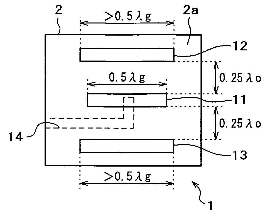
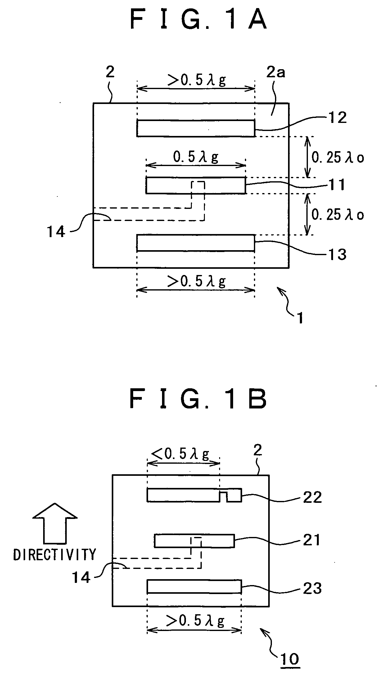
[0038]FIG. 1A is a view showing a configuration of a slot antenna that forms the basis of the antenna apparatus specified as the embodiment of the present invention. A slot antenna 1 shown in FIG. 1A has, at an approximately center position of a planar printed circuit board 2, a driven element 11 given a feed, and before and behind the driven element 11, parasitic elements 12 and 13 respectively given no feed. Then, the slot antenna 1 having the above configuration is supposed to be capable of radiating radio waves from the driven element 11.

[0039] The driven element 11 is in the form of a slot (a slit) provided in a conducto...


PUM


Abstract

In order to have an antenna apparatus small in size and capable of switching its directivity pattern to be adaptive to multiple frequencies, the present invention provides an antenna apparatus having a first antenna element formed at an approximately center position of a planar printed circuit board and second antenna elements formed before and behind the first antenna element. It is possible to construct an antenna in which the first antenna element functions as a radiator and the second antenna elements function as a director or a reflector, respectively, by changing electrical length of the second antenna elements. The antenna becomes adaptive to multiple frequencies by feeding the second antenna elements at different phases to have the second antenna elements functioning as radiators.

Description

CROSS REFERENCES TO RELATED APPLICATIONS [0001] The present document is based on Japanese Priority Document JP 2004-016185, filed in the Japanese Patent Office on Jan. 23, 2004, the entire contents of which being incorporated herein by reference. BACKGROUND OF THE INVENTION [0002] 1. Field of the Invention [0003] The present invention relates to an antenna apparatus capable of performing a switching of a directivity pattern. [0004] 2. Description of Related Art [0005] Conventionally, it is known that a use of an antenna having no directivity pattern leads to a degradation of a communication quality with an interference wave caused by a reflection from a building wall etc. in a multi path propagation environment in which multiple radio waves are available. Thus, an antenna apparatus capable of turning a directivity pattern in a specific direction has attracted attention. [0006] A phased array antenna apparatus shown in FIG. 13 and an adaptive array antenna apparatus shown in FIG. 14 ...

Claims


Application Information

Patent Timeline
IPC IPC(8): H01Q19/28G01S3/16H01Q3/24H01Q3/34H01Q3/44H01Q5/00H01Q13/08H01Q13/10H01Q19/30H01Q21/00
CPCH01Q3/44H01Q19/30H01Q13/10H01Q3/24H01Q13/08H01Q21/00
Inventor MORI, KOHEI
Owner SONY CORP
Why Eureka
Try Eureka