Antenna apparatus
a technology of antenna apparatus and antenna elements, which is applied in the direction of antenna details, polarised antenna unit combinations, antennas, etc., can solve the problems of complicated solid arrangement of antenna elements, and achieve the effects of saving space, simplifying the structure, and reducing the size of the antenna apparatus
- Summary
- Abstract
- Description
- Claims
- Application Information
AI Technical Summary
Benefits of technology
Problems solved by technology
Method used
Image
Examples
first embodiment
[0034]An antenna apparatus according to a first embodiment of the present invention can be applied to a location-free visual-audio system that has place shift function, this system being, for example, called LocationFree (registered trademark of Sony Corporation) with which the user can watch and listen to content such as television programs wherever he or she is. The minimum structural components of the place shift visual-audio system are a base station that is a content transmitting apparatus and a receiving apparatus (also referred to as a location free player or a client) that provide picture and sound to the user.
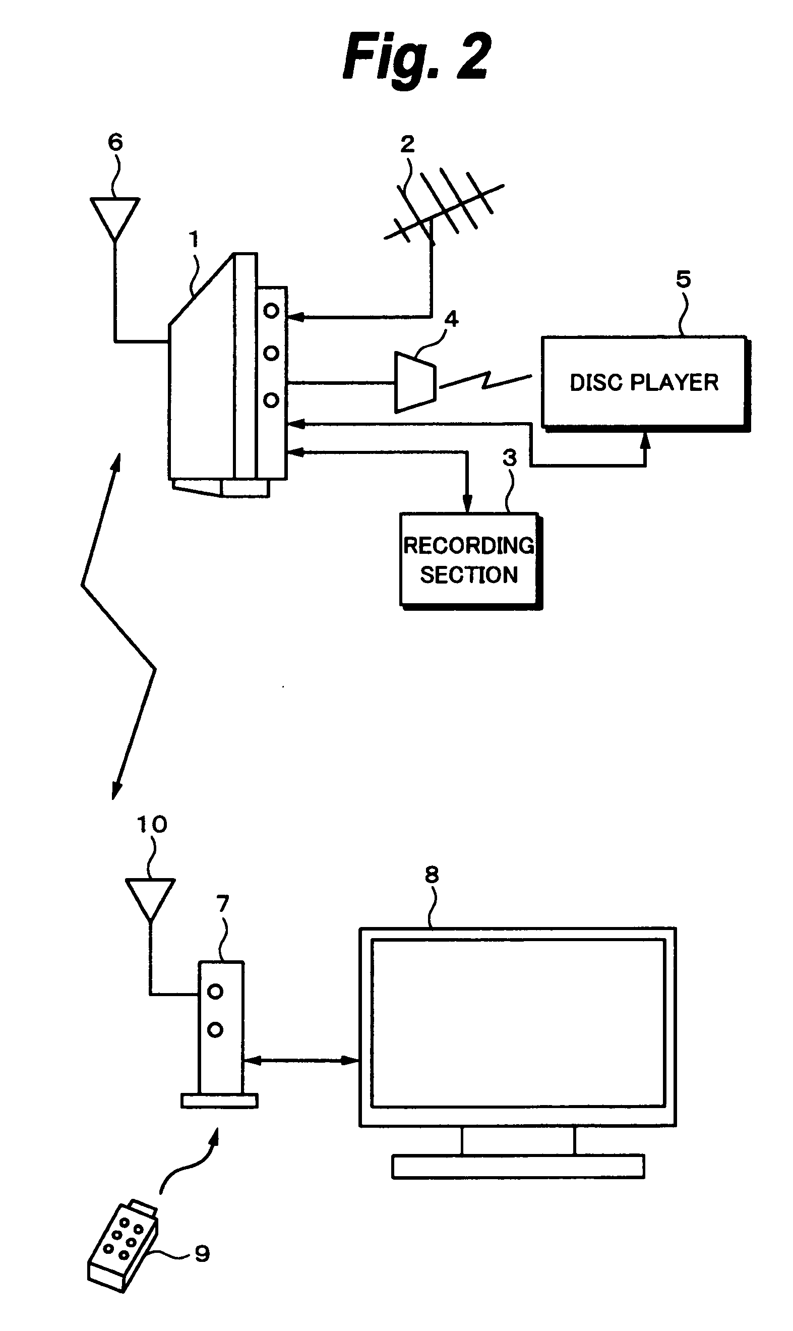
[0035]First, with reference to FIG. 2, the structure of a content transmitting and receiving system using wireless LAN will be briefly described. Connected to a base station 1 that is the content transmitting apparatus is a television antenna 2. Thus, the base station 1 can receive television broadcast content (eg, analog television broadcast content). In addition, the...
second embodiment
[0083]A second embodiment of the present invention is an antenna apparatus having a plurality of antennas disposed perpendicular to each other. In the antenna apparatus according to the second embodiment, by combining gain patterns of individual antennas, variation of antenna gain patterns is increased. Like the first embodiment, the antenna apparatus according to the second embodiment can be used for the radio base station 21 and the radio terminal 22.
[0084]Next, with reference to FIG. 9, the structure of the antenna apparatus according to the second embodiment will be described. FIG. 9 is a schematic diagram showing the structure of the antenna apparatus according to the second embodiment viewed from the top of the antenna apparatus in the case that principal surfaces of a substrate 11 stand upright. In the second embodiment, it is assumed that the antenna apparatus has four antennas 70a, 70b, 70c, and 70d (hereinafter, they are generally designated as antennas 70 unless otherwise...
PUM
 Abstract
Description
Claims
Application Information
 - R&D
- Intellectual Property
- Life Sciences
- Materials
- Tech Scout
- Unparalleled Data Quality
- Higher Quality Content
- 60% Fewer Hallucinations
Browse by: Latest US Patents, China's latest patents, Technical Efficacy Thesaurus, Application Domain, Technology Topic, Popular Technical Reports.
© 2025 PatSnap. All rights reserved.Legal|Privacy policy|Modern Slavery Act Transparency Statement|Sitemap|About US| Contact US: help@patsnap.com


