Distributed forwarding in virtual network devices

a virtual network device and forwarding technology, applied in the field of network work, can solve the problems of inconvenient network management, increased complexity, and inability to manage the link in question, and achieve the effect of avoiding the need for network management and complexity

Active Publication Date: 2005-07-28
CISCO TECH INC
View PDF99 Cites 139 Cited by
  • Summary
  • Abstract
  • Description
  • Claims
  • Application Information

AI Technical Summary

Problems solved by technology

However, if multiple redundant links are active at the same time, management of those links may be undesirably complicated (e.g., due to the need to avoid bridging loops).
This complexity extends to other situations in which multiple redundant componen

Method used


Image

  • Distributed forwarding in virtual network devices
  • Distributed forwarding in virtual network devices
  • Distributed forwarding in virtual network devices

Examples


Embodiment Construction

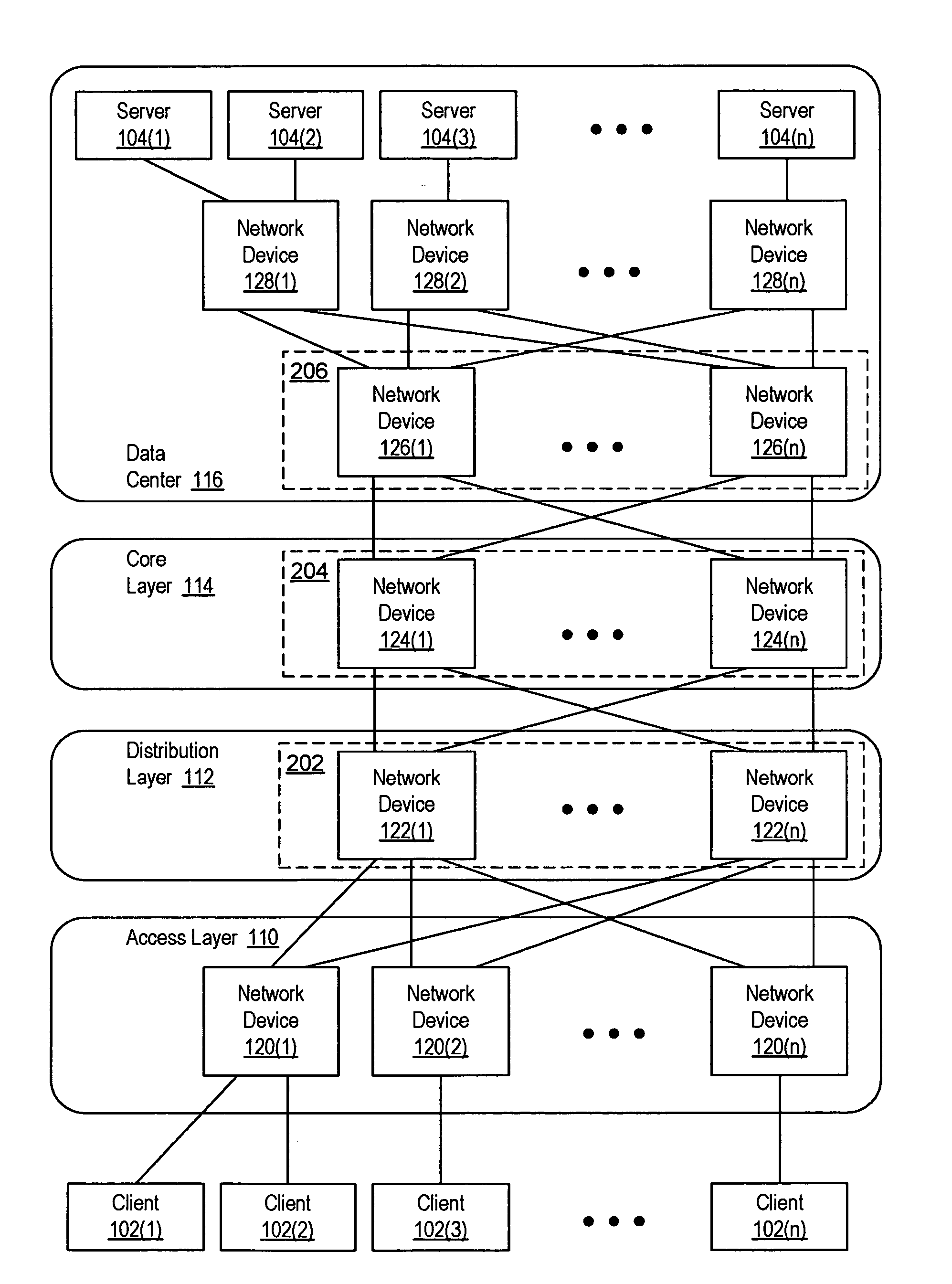
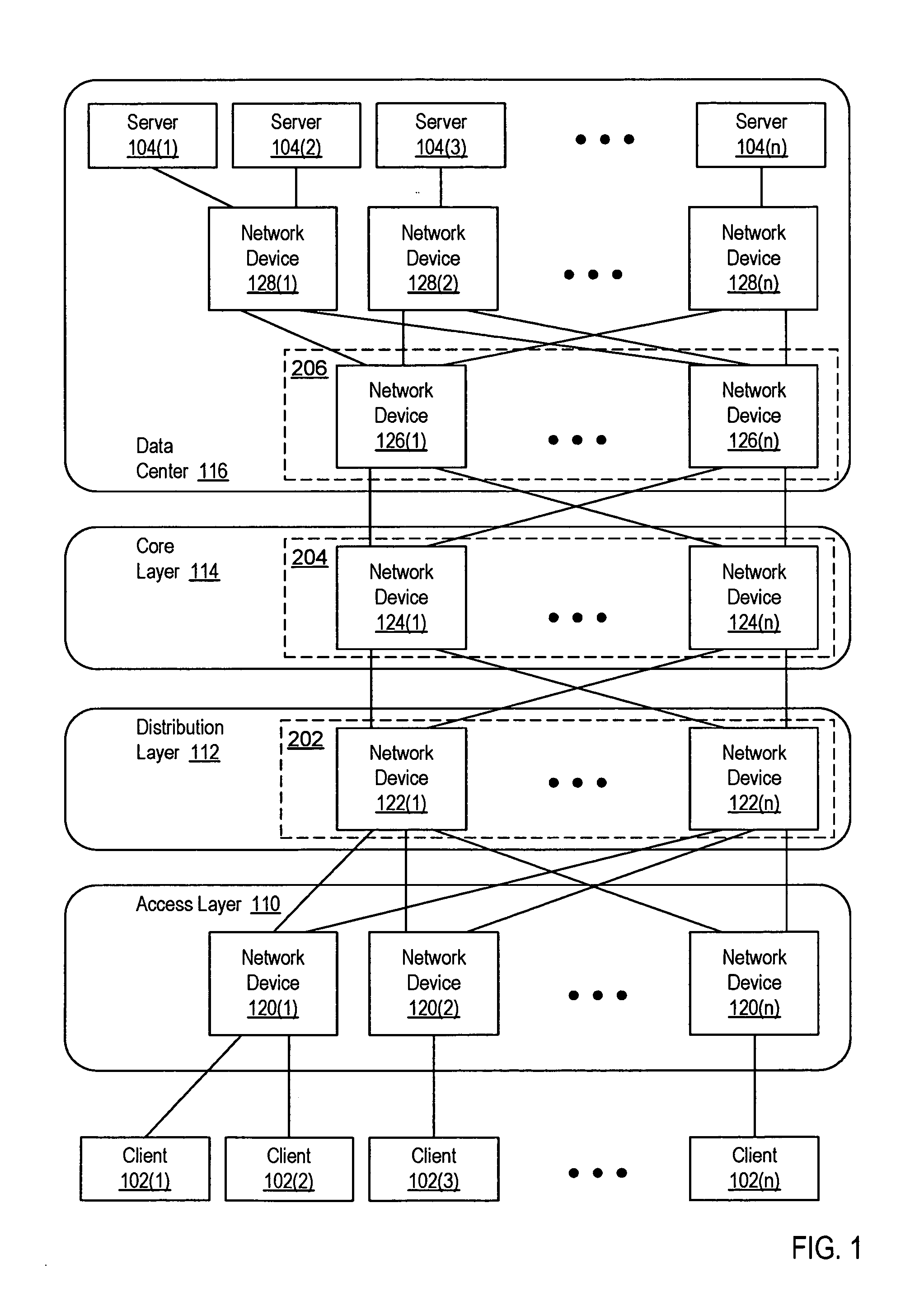
[0026]FIG. 1 is a block diagram of a network. In FIG. 1, several clients 102(1)-102(n) communicate with each other and with several servers 104(1)-104(n) via a network. Clients 102(1)-102(n) can include a variety of different devices that access networked services. For example, client 102(1) can be a cell phone, client 102(2) can be a personal computer, and client 102(n) can be a Personal Digital Assistant (PDA). Servers 104(1)-104(n) provide various services, such as various software-based services and / or access to shared storage devices.

[0027] The network coupling clients 102(1)-102(n) and servers 104(1)-104(n) is described in terms of several network layers. The layer closest to clients 102(1)-102(n) is access layer 110. Access layer 110 includes several network devices 120(1)-120(n). In this example, access layer 110 is the primary layer at which packets enter the network from clients 102(1)-102(n).

[0028] Distribution layer 112 aggregates flows received via access layer 110 an...


PUM


Abstract

A virtual network device sub-unit includes an interface to a virtual network device link and a distributed forwarding module. The interface receives a packet, and the distributed forwarding module forwards the packet received by the interface. The distributed forwarding module performs an ingress lookup if the packet includes a multicast destination address and an egress lookup if the packet includes a unicast destination address. If the packet includes a multicast destination address, the distributed forwarding module replicates the packet for each of several outgoing VLANs associated with the multicast destination address. If an additional multicast packet is received via an interface that is not coupled to a virtual network device link, the distributed forwarding module sends at most one copy of the additional multicast packet via the virtual network device link.

Description

CROSS-REFERENCE TO RELATED APPLICATIONS [0001] This application is a continuation-in-part of U.S. patent application Ser. No. 10 / 666,306, entitled “Virtual Network Device,” filed Sep. 12, 2003, and naming Michael Smith, Ali Golshan, Jeffrey Ym Wang, Neelima Mehta, and Venkatesh Janakiraman as inventors, which is hereby incorporated by reference herein in its entirety.BACKGROUND OF THE INVENTION [0002] 1. Field of the Invention [0003] The present invention relates to networking and, more specifically, to performing distributed forwarding in a virtual network device. [0004] 2. Description of the Related Art [0005] In order to provide increased network reliability, redundant switches and links are often included in a network. If a switch or link fails, a redundant switch or link, already in place within the network, is quickly enabled to replace the failed switch or link. Since the redundant switch or link is typically enabled as a replacement more quickly than the failed component can...

Claims


Application Information

Patent Timeline
IPC IPC(8): H04L45/28H04L12/46H04L12/56H04L45/18H04L45/586
CPCH04L12/46H04L12/4641H04L41/0806H04L45/742H04L45/00H04L45/18H04L45/586H04L41/082H04L41/122
Inventor DONTU, SITARAMMUSHTAQ, FAISALBHIDE, SHREERAMSMITH, MICHAEL R.GOLSHAN, ALI
Owner CISCO TECH INC
Why Eureka
Try Eureka