Multi-port optical connection terminal

a multi-port, optical connection technology, applied in the direction of optical light guides, fibre mechanical structures, instruments, etc., can solve the problems of difficult to enter the closure, difficult to reconfigure the optical fiber connection in the aerial splice closure, and difficulty in entering the closure process

Active Publication Date: 2005-07-28
CORNING OPTICAL COMM LLC
View PDF34 Cites 253 Cited by
  • Summary
  • Abstract
  • Description
  • Claims
  • Application Information

AI Technical Summary

Benefits of technology

[0010] To achieve the foregoing and other objects, and in accordance with the purposes of the invention as embodied and broadly described herein, the present invention provides various embodiments of a factory manufactured and assembled multi-port optical connection terminal for readily interconnecting optical fibers of one or more pre-connectorized fiber optic drop cables with respective optical fibers of a fiber optic distribution cable at a branch point in a fiber optic communications network. In various embodiments, the multi-port optical connection terminal is configured to receive one or more pre-connectorized drop cables extending from an outside plant connection terminal, such as an aerial closure, a below-grade closure, an above g

Problems solved by technology

In particular, it is often difficult to enter the closure and to identify an optical fiber of the distribution cable to be interconnected with an optical fiber of a particular drop cable.
In either case, the process of entering and configuring the aerial splice closure is not only time consuming, but frequently must be accomplished by a highly skilled field technician at significant cost and under field working conditions that are less than ideal.
Reconfiguring optical fiber connections in an aerial splice closure is especially difficult, particularly in instances where at least some of the optical fibers of the distribution cable extend uninterrupted through the closure, commonly referred to as a “taut-sheath” or “express” application, since the closure cannot be readily removed from the distribution cable.
Further, once the optical connections are made, it is often labor intensive, and therefore costly, to reconfigure the existing optical connections or to add additional optical connections.
However, even wi

Method used


Image

  • Multi-port optical connection terminal
  • Multi-port optical connection terminal
  • Multi-port optical connection terminal

Examples


Embodiment Construction

[0026] The present invention will now be described more fully hereinafter with reference to the accompanying drawings in which exemplary embodiments of the invention are shown. However, this invention may be embodied in many different forms and should not be construed as limited to the embodiments set forth herein. These exemplary embodiments are provided so that this disclosure will be both thorough and complete, and will fully convey the scope of the invention to those skilled in the art. Like reference numbers refer to like elements throughout the various drawings.

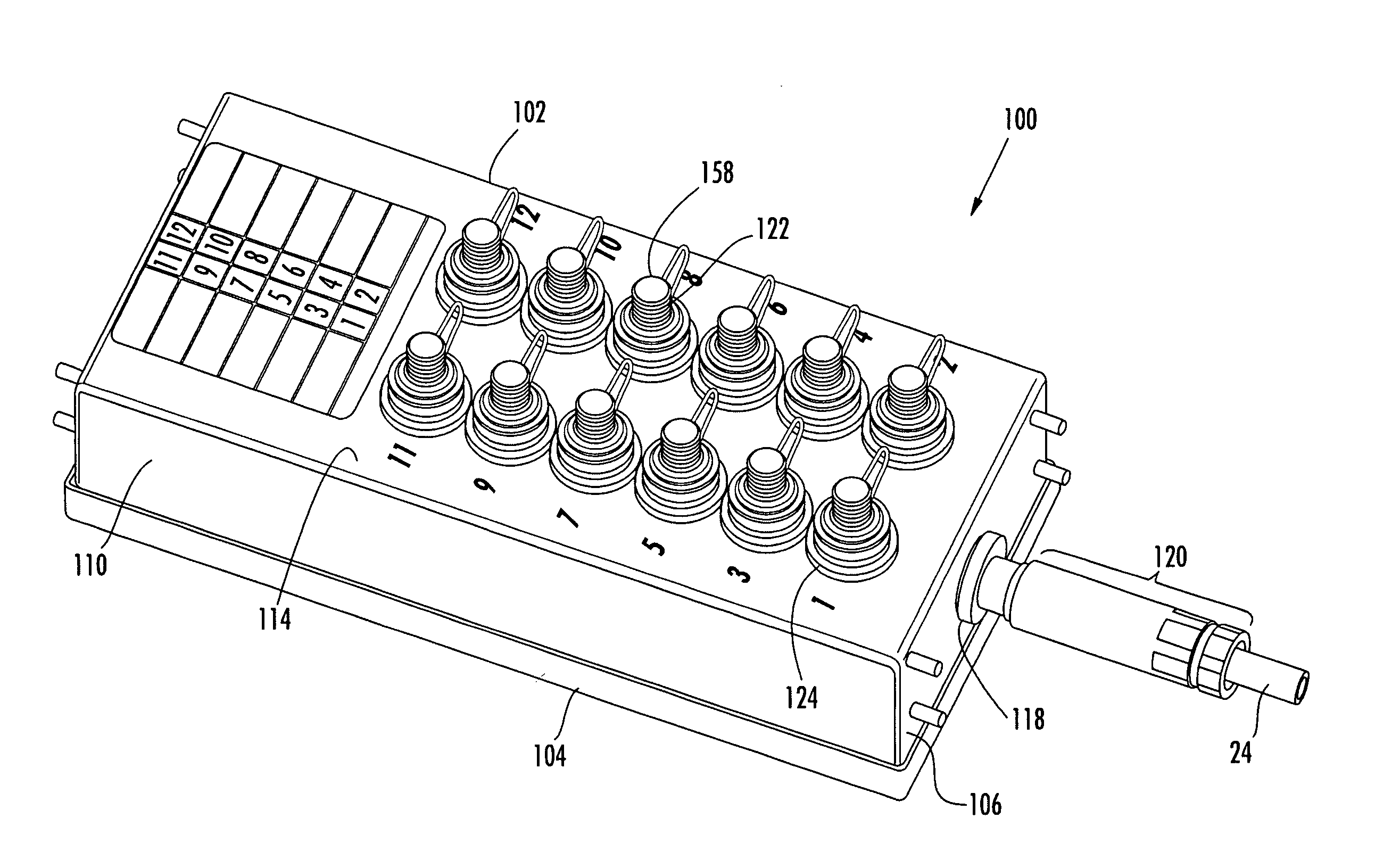
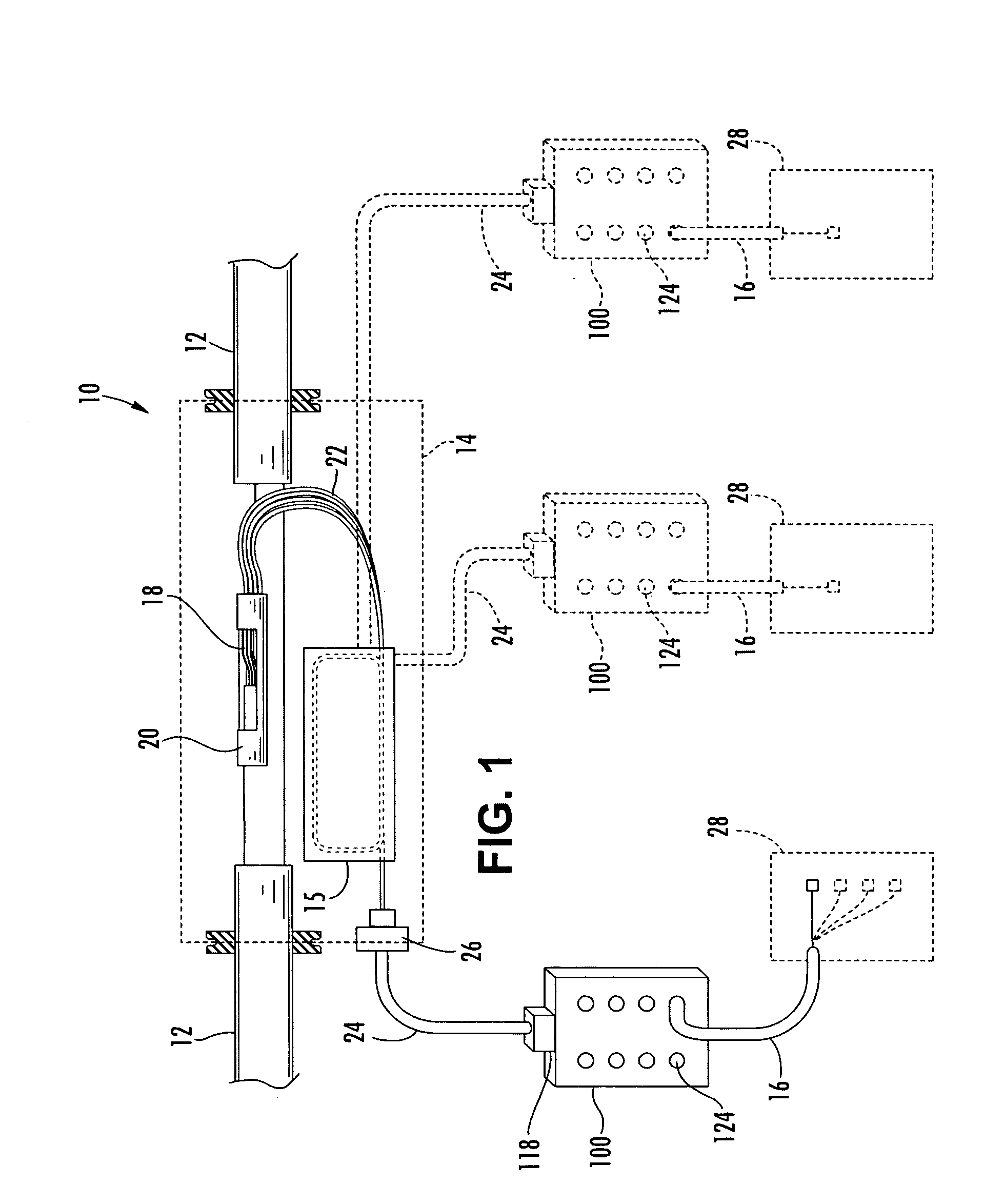
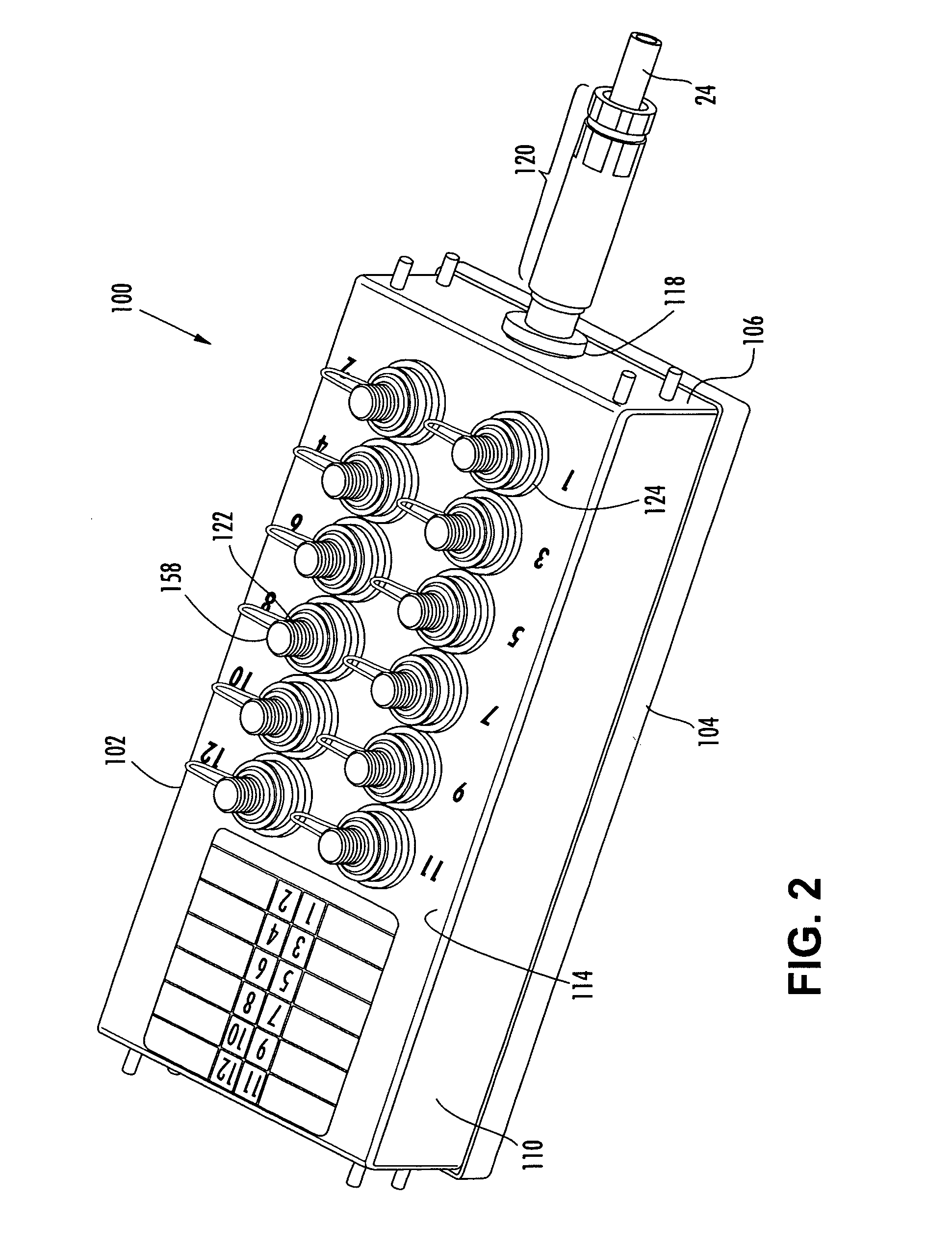
[0027] The present invention provides various embodiments of a multi-port optical connection terminal comprising a plurality of connector ports that receive optical connectors for interconnecting one or more pre-connectorized fiber optic drop cables to a distribution cable at a branch point in a fiber optic communications network. The various embodiments of the present invention may be applied in an optical “fiber-to-t...


PUM


Abstract

A multi-port optical connection terminal for use as a branch point in a fiber optic communications network at a distance from a mid-span access location provided on a distribution cable having a plurality of optical fibers. The multi-port terminal includes a base and a cover affixed to the base. A stub cable port formed through one of the base and the cover receives a stub cable having at least one optical fiber extending continuously from the multi-port terminal to the mid-span access location. A first end of the optical fiber is optically connected to a respective optical fiber of the distribution cable at the mid-span access location and a fiber optic connector is mounted upon the second end. At least one connector port is provided on the multi-port terminal for receiving the fiber optic connector and a connectorized end of a fiber optic drop cable extending from the multi-port terminal.

Description

BACKGROUND OF THE INVENTION [0001] 1. Field of the Invention [0002] The present invention relates generally to an enclosure for interconnecting optical fibers in a fiber optic communications network, and more particularly, to a multi-port optical connection terminal for interconnecting optical fibers of one or more pre-connectorized fiber optic drop cables with optical fibers of a fiber optic distribution cable at a branch point in a fiber optic network. [0003] 2. Description of the Related Art [0004] Optical fiber is increasingly being used for a variety of broadband applications including voice, video and data transmissions. As a result of the ever-increasing demand for broadband communications, fiber optic networks typically include a large number of mid-span access locations at which one or more optical fibers are branched from a distribution cable. These mid-span access locations provide a branch point from the distribution cable leading to an end user, commonly referred to as ...

Claims


Application Information

Patent Timeline
IPC IPC(8): G02B6/00G02B6/38G02B6/44
CPCG02B6/3897G02B6/4466G02B6/4451G02B6/4441G02B6/501G02B6/475
Inventor BLACKWELL, CHOIS A. JR.MENKE, BRETT A.REAGAN, JASON B.STRAUSE, KEVIN L.SMITH, KELLY J.
Owner CORNING OPTICAL COMM LLC
Why Eureka
Try Eureka