
Robot

a robot and portable telephone technology, applied in the field of robots, can solve the problems of increasing the price, requiring considerable time, and not being able to direct communication between the portable telephone and the robo

Inactive Publication Date: 2005-07-28
FUJITSU LTD
View PDF16 Cites 145 Cited by
  • Summary
  • Abstract
  • Description
  • Claims
  • Application Information

AI Technical Summary

Benefits of technology

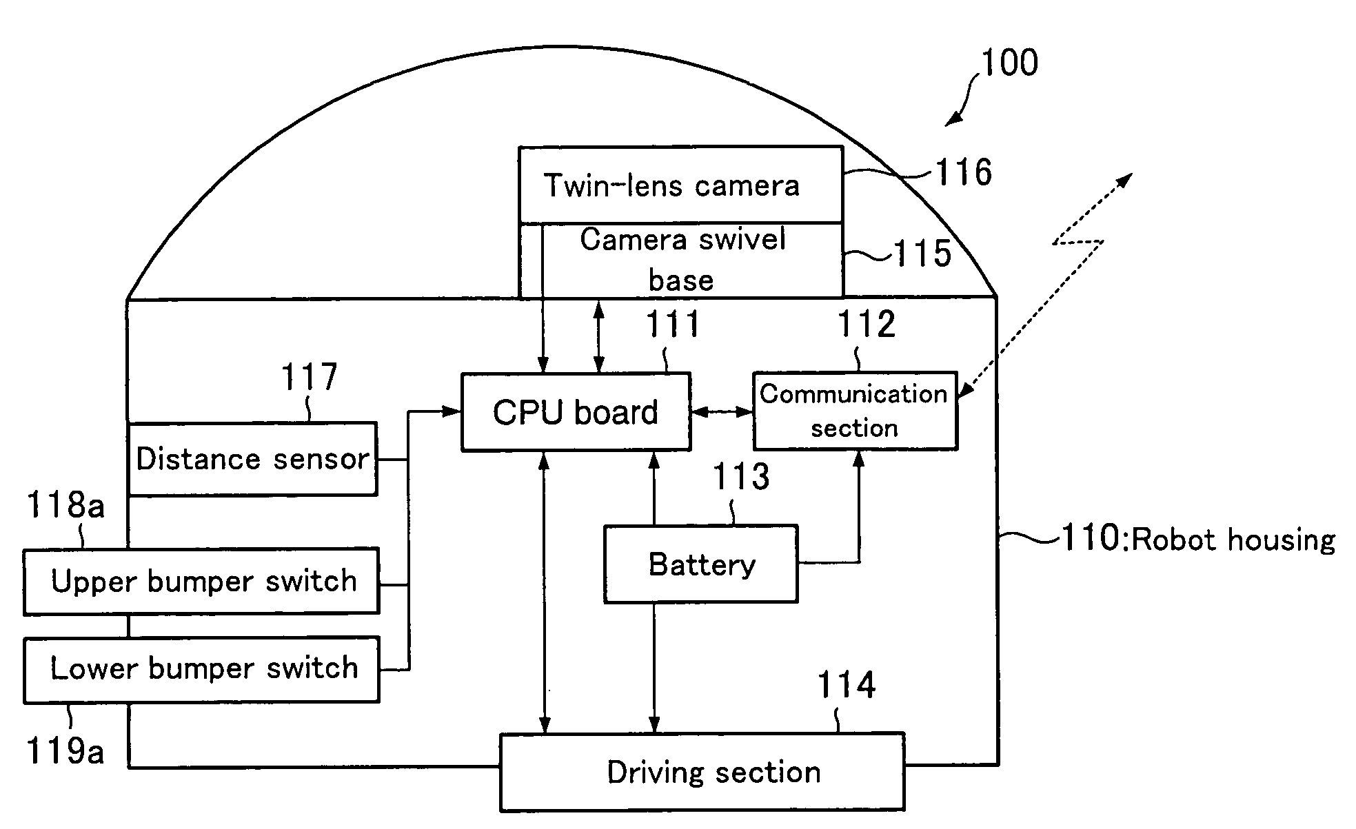
[0008] It is an object of the present invention to provide a robot having the structure suitable for freely moving about in the environment where there is an obstacle within the house, for example.

Problems solved by technology

When a robot is introduced into the home, it is unfavorable that a new remote controller is prepared for operation of the robot because the price is correspondingly increased.
However, when the portable telephone is employed as the remote controller, the direct communication between the portable telephone and the robot is not enabled, in which a command inputted by a key operation of the portable telephone is once transmitted to the base station, and then transmitted from the base station to the robot.
In this case, a considerable time is required from operating the portable telephone till the arrival of the command to the robot, giving rise to various inconveniences.
For example, when an image is delivered from the robot, an obstacle may be actually imminent to the robot's eyes, even though the obstacle is farther away from the robot in the advancement direction on the image, in which there is a possible situation that a change-direction command for avoidance issued is too late.
In this constitution, if the robot has a round shape, the robot can turn on the spot upon contact with the obstacle, while if the robot has an angular shape, the robot tries to turn after contact with the obstacle, but can not change direction successfully, causing a risk that the robot becomes immovable on the spot.
For example, when one wants to move the robot within the house from the outside by issuing a movement command, employing a packet communication function of the portable telephone, it is difficult to enable the robot to perform a smooth movement.

Method used


Image

  • Robot
  • Robot
  • Robot

Examples


Embodiment Construction

[0040] The preferred embodiments of the present invention will be described below.

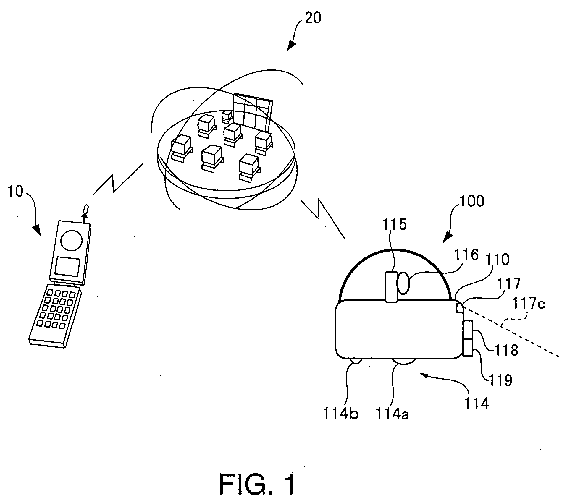
[0041]FIG. 1 is a view showing a robot according to one embodiment of the present invention, and a control system controlling the robot, employing a packet communication function of the portable telephone.

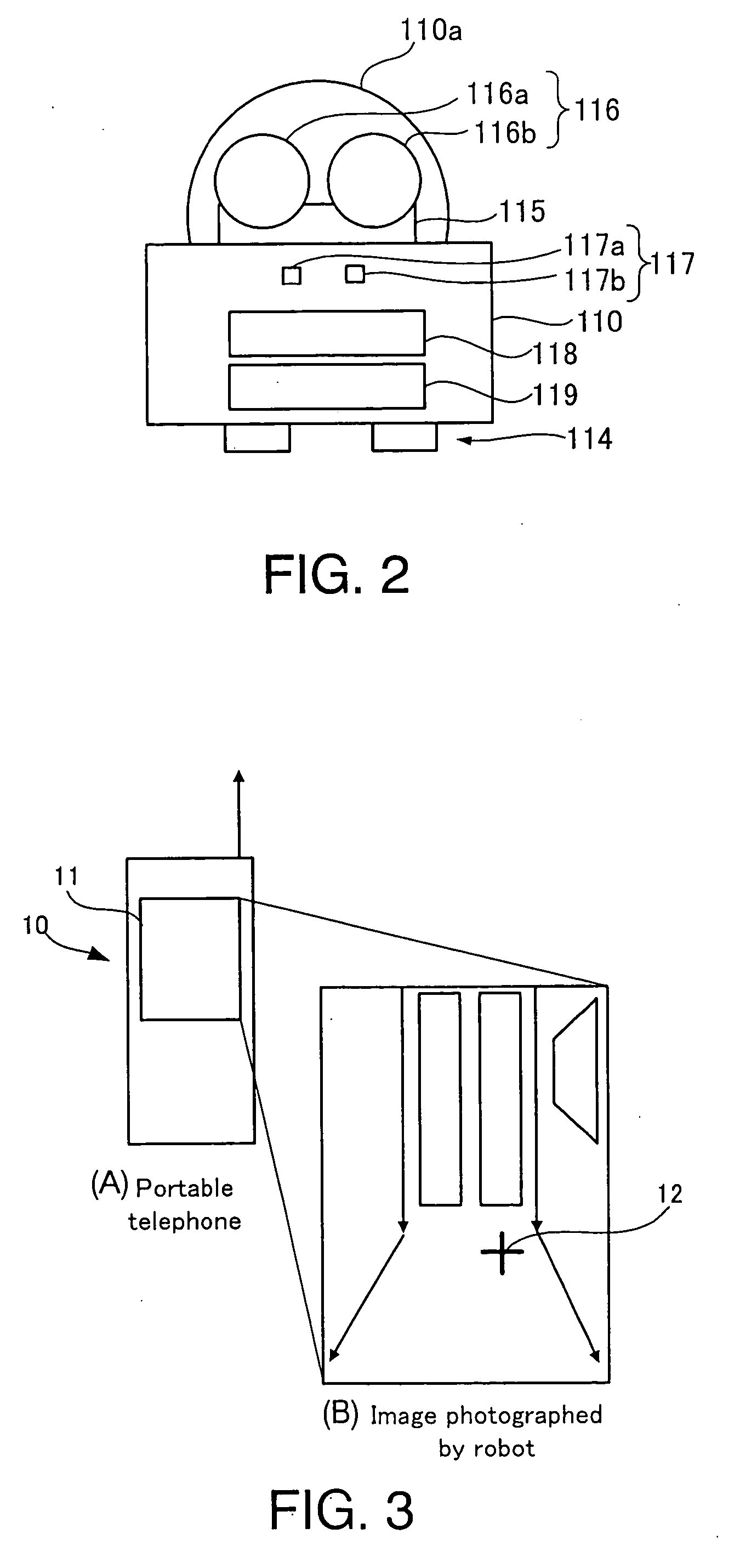
[0042] Each of the portable telephone 10 and the robot 100 has a function of making the packet communication with a base station 20. The robot 100 has a function of transmitting through the packet communication an image photographed by a camera 116 mounted on the robot via the base station 20 to the portable telephone 10. Also, the portable telephone 10 has a function of displaying the cursor indicating the movement target position of the robot 100 on the transmitted image by a key operation, and a function of transmitting the coordinate information of the cursor on the image via the base station 20 to the robot 100.

[0043] Referring to FIGS. 1 and 2, the structure of this robot 100 will be describe...


PUM


Abstract

The present invention aims to provide a robot having the structure suitable for freely moving about in the environment where there is an obstacle within the house, for example. The robot includes a communication section transmitting by wireless an image taken by the camera to a base station, and via the base station to a communication terminal making the radio communication with the base station, and receiving by wireless the movement target position information specified on the image by an operation of the communication terminal via the base station, and a motion control section that moves the robot up to a movement target position specified by the movement target position information acquired in the communication section.

Description

TECHNICAL FIELD [0001] The present invention relates to a robot that can freely move, and more particularly to a robot having the structure suitable for a small robot for home use. BACKGROUND ART [0002] In recent years, various apparatuses are equipped with a remote controller for controlling the operation of apparatus. In the present state of affairs, each house has more than one remote controller. Also, various robots have been recently developed, and entered each home. When a robot is introduced into the home, it is unfavorable that a new remote controller is prepared for operation of the robot because the price is correspondingly increased. Since the portable telephones have broadly spread in recent years, a portable telephone may be utilized as the remote controller, instead of preparing the new remote controller, by providing the robot with the same communication functions as those of the portable telephone. In this case, in consideration of the service charge, it is beneficia...

Claims


Application Information

Patent Timeline
IPC IPC(8): A63H11/00B25J5/00B25J13/08G05D1/00G05D1/02G06F19/00G06N3/00
CPCG05D1/0251G06N3/008G05D2201/0207G05D1/0285
Inventor KANDA, SHINJIMURASE, YUICHIIWASHITA, SUMIHISASHIMIZU, KATSUTOSHISAWASAKI, NAOYUKIOKABAYASHI, KEIJU
Owner FUJITSU LTD
Learn More