
Identification means for swab applicator

a technology of identification means and swab, which is applied in the direction of swab, medical devices, tampons, etc., can solve the problems of virtually impossible to distinguish the end of the container from the other, the position of the fracture line cannot be seen or accurately determined, and it is virtually impossible to distinguish the end of the hollow tubular body from the other end, etc., to achieve accurate determination of the position of the fracture lin

Inactive Publication Date: 2005-08-04
TSAUR GARRY
View PDF12 Cites 17 Cited by
  • Summary
  • Abstract
  • Description
  • Claims
  • Application Information

AI Technical Summary

Benefits of technology

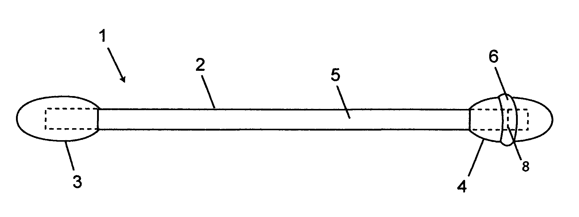
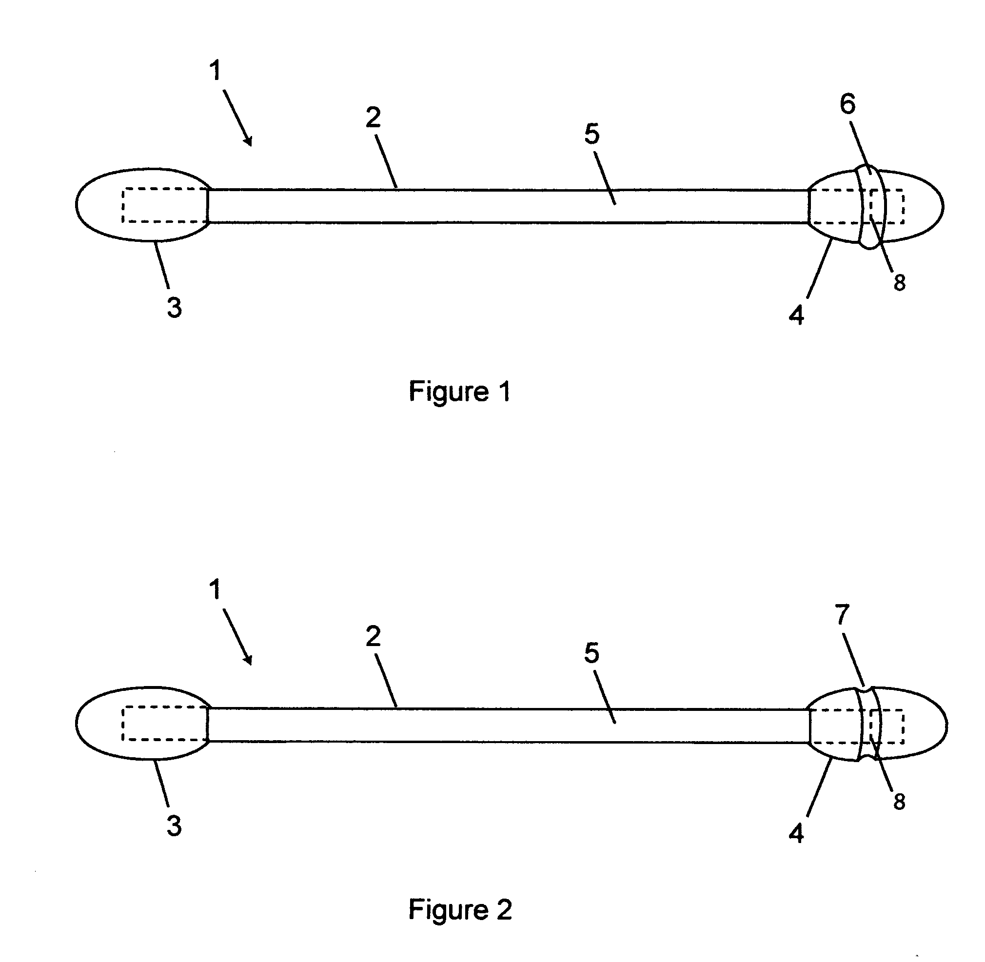
[0006] The present invention is an identification means for swab applicator that enables a person to distinguish one end of the swab applicator from the other end even with impaired vision or in low light conditions. Furthermore, the identification means enables one to accurately determine the position of a fracture line on the swab applicator for release of the fluid enclosed within the swab applicator. In the preferred embodiment, the identification means for swab applicator comprises of a raised ring embossed on the applicator tip positioned near the fracture line on the swab applicator that can be seen and felt. In another embodiment, the identification means for swab applicator comprises of a ring of channel around the applicator tip positioned near the fracture line on the swab applicator that can be seen and felt.

Problems solved by technology

When both ends of the hollow tubular body are each wrapped by an applicator tip, it becomes virtually impossible to distinguish which end of the container has the fracture line that needs to be broken open to release the fluid.
In addition, even when only one end is wrapped by the applicator tip, the position of the fracture line cannot be seen or accurately determined.
Furthermore, if the hollow tubular body with both ends wrapped by an applicator tip is being used by a person with impaired vision or in low light condition, it also becomes virtually impossible to distinguish one end of the hollow tubular body from the other even if one end is marked with a different color applicator tip.
The position of the fracture line also cannot be determined in these situations.

Method used


Image

  • Identification means for swab applicator
  • Identification means for swab applicator

Examples


Embodiment Construction

[0009] The following description and figures are meant to be illustrative only and not limiting. Other embodiments of this invention will be apparent to those of ordinary skill in the art in view of this description.

[0010]FIG. 1 shows a preferred embodiment of identification means for swab applicator. The swab applicator 1 comprises a hollow elongated tubular body 2 with an applicator tip 3, 4 affixed to each of its two ends and encloses a fluid 5 within its hollow elongated tubular body 2. A fracture line 8 is formed near one end of the hollow elongated tubular body 2 to allow the elongated tubular body 2 to be broken open at the fracture line 8. In the preferred embodiment, the identification means is a raised ring 6 embossed on the applicator tip 4 that can be seen and felt.

[0011] The raised ring 6 is position near the fracture line 8 on the elongated tubular body 2. The raised ring 6 around the applicator tip 4 can be painted with a color that can be easily seen by someone wit...


PUM


Abstract

An identification means for swab applicator that enables a person to distinguish one end of the swab applicator from the other end even with impaired vision or in low light conditions. In addition, the identification means enables one to accurately determine the position of a fracture line on the swab applicator for release of the fluid enclosed within the swab applicator. The identification means for swab applicator comprises of a raised ring or a ring of channel on the applicator tip positioned near the fracture line on the swab applicator that can be seen and felt.

Description

BACKGROUND [0001] 1. Field of Invention [0002] The present invention relates generally to identification means for swab applicator. More specifically, the present invention relates to identification means positioned on the swab or tip. [0003] 2. Description of Related Art [0004] Swab applicator generally comprises of an elongated tubular body with an applicator tip affixed to one or both of its ends. The elongated tubular body may be made of wood, paper, or plastic and may be a solid member or a hollow tube. The applicator tip may be a foam tip, a sponge, a wad of cotton, or a brush. Swab applicator with a hollow tubular body may also enclose a fluid with one or both ends sealed. [0005] Swab applicator that contains a fluid may have one or both ends sealed with an applicator tip affixed to one or both ends. An opening means such as a fracture line may be provided near one end such that when the hollow tubular body is broken open at the fracture line, the fluid will flow out of the h...

Claims


Application Information

Patent Timeline
IPC IPC(8): A61F13/38A61F13/40
CPCA61M35/006A61F13/38
Inventor TSAUR, GARRY
Owner TSAUR GARRY
Learn More