
Storage subsystem

a storage subsystem and subsystem technology, applied in the field of storage subsystems, can solve the problems of wasting such data transfer, affecting the reliability of data, and requiring longer restoration time, so as to achieve the effect of restoring data by either technique, and saving tim

Inactive Publication Date: 2005-08-04
HITACHI LTD
View PDF22 Cites 68 Cited by
  • Summary
  • Abstract
  • Description
  • Claims
  • Application Information

AI Technical Summary

Benefits of technology

[0013] It is an object of the present invention to provide a storage system for restoring data at a remote site without imposing a burden on the host when restoring the data stored in the storage system.
[0016] According to the present invention, when restoring the data stored in the storage system, it is possible to restore data to its predetermined state at a remote site without imposing any burden on the host within a short time.

Problems solved by technology

It is wasteful to transfer such data, and it takes longer time to restore.
As regards data which has been updated during a period of time from a time at which backup of data is carried out to a time at which the storage system develops a failure, however, the data cannot be restored by either technique.
For this reason, load on the host is great and it takes a long time to process.

Method used


Image

  • Storage subsystem
  • Storage subsystem
  • Storage subsystem

Examples


Embodiment Construction

[0041] Hereinafter, with reference to the drawings, the description will be made of one embodiment of the present invention.

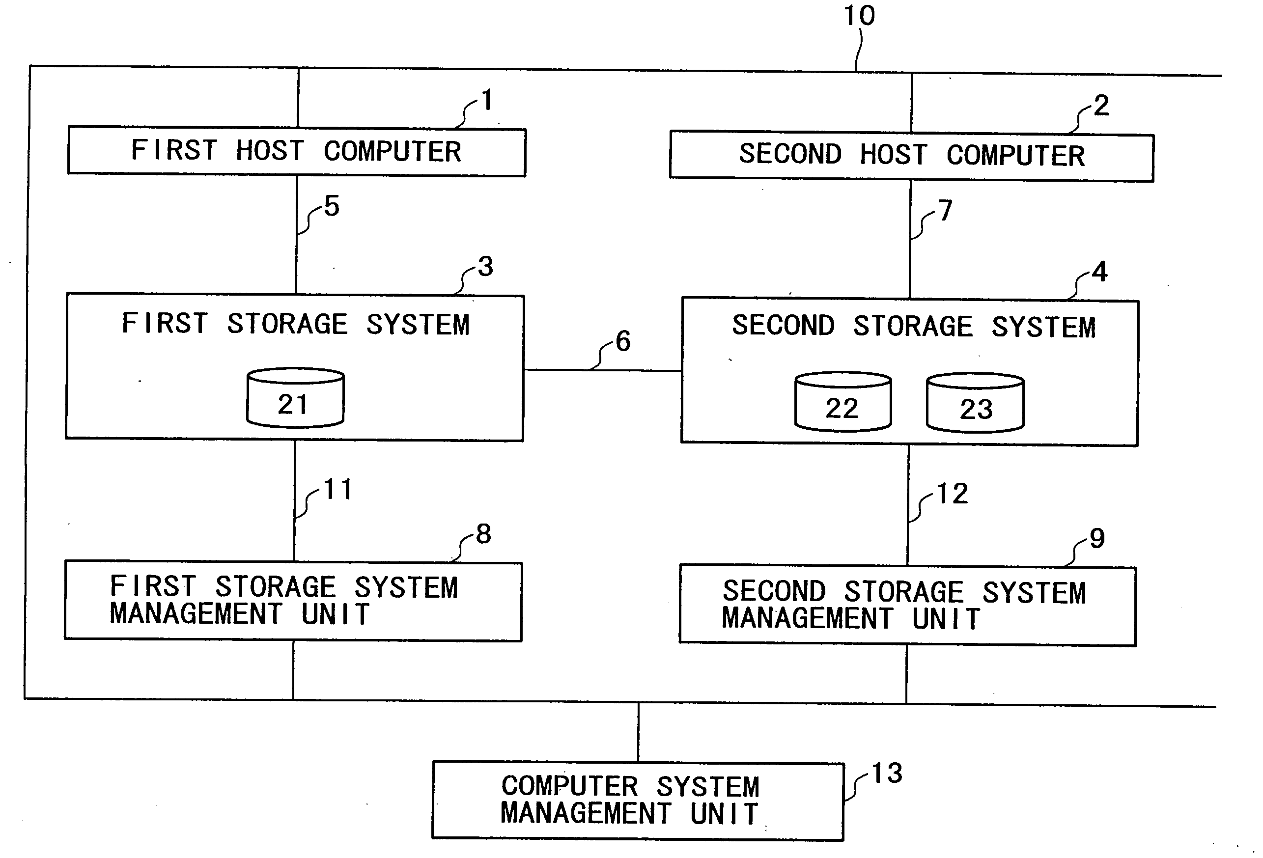
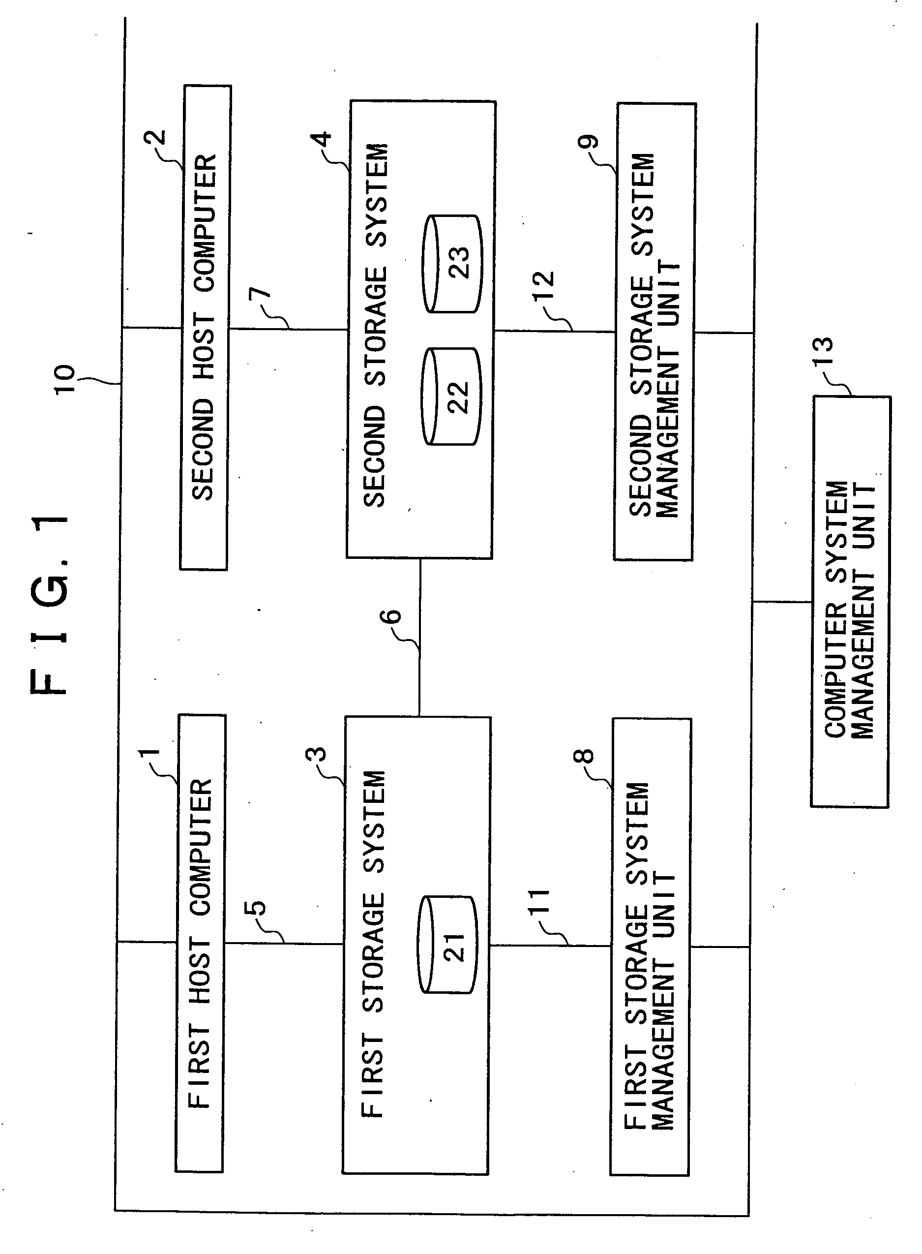
[0042]FIG. 1 is a block diagram showing a computer system according to one embodiment.

[0043] This computer system includes a first host computer 1 (hereinafter, referred to as host 1), a second host computer 2 (hereinafter, referred to as host 2), a first storage system 3 (hereinafter, referred to as storage system 3 simply) to be connected to the host 1 via a communication channel 5, a second storage system 4 (hereinafter, referred to as storage system 4 simply) to be connected to the host 2 via a communication channel 7 and to be connected to the storage system 3 via a communication channel 6, a first storage system management unit 8 to be connected to the storage system 3 via a communication channel 11, a second storage systemanagement unit (hereinafter, referred to as management unit) 9 to be connected to the storage system 4 via a communication channel 1...


PUM


Abstract

The data up to a point of time whereat failure has occurred will be restored at high speed at a remote site without imposing any burden on a host. The first storage system on the master side processes an I / O request from the host, and as a result of I / O processing to the second storage system on the remote side, transmits the update data. The second storage system retains data received from the first storage system as update log data. The host transmits a command for settling a state of an application to the first storage system as data, and the first storage system transmits the data to the second storage system. The host and the second storage system both retain an identifier corresponding to the command, and relate the identifier to the log data. Thereby, the host designates the identifier at any given time, whereby the second storage system restores the data at any given time.

Description

BACKGROUND OF THE INVENTION [0001] 1. Field of the Invention [0002] The present invention relates to a storage subsystem, and more particularly to remote copying of a storage subsystem for acquiring a write I / O log and a method of restoring a log during a disaster. [0003] 2. Description of the Prior Arts [0004] A computer system has become commercially practical in which a computer and a storage system are connected together through a network, and data to be processed by the computer is transmitted and received via the network and is stored in the storage system. In online processing and batch processing that are to be carried out by the computer system, there may enter a situation in which these processing abnormally terminates by program bugs, failure of the storage system and the like to cause contradictions in the data stored in the storage system. Also, the data stored in the storage system may be erased by an artificial mistake. [0005] In order to recover data of the computer ...

Claims


Application Information

Patent Timeline
Patent Type & Authority Applications(United States)
IPC IPC(8): G06F11/00G06F12/00G06F11/14
CPCG06F11/1469G06F11/1471G06F11/1464G06F2201/855G06F11/2071
Inventor EGUCHI, YOSHIAKIYAMAMOTO, YASUTOMOARAKAWA, HIROSHIHIRAKAWA, YUSUKE
Owner HITACHI LTD
Learn More