Sole structure for a shoe

a technology for shoe soles and soles, applied in the field of shoe sole structures, can solve the problems of increasing the burden on the mp joints, increasing the burden on the knee joints too, and causing injury to the foot joints and the knee joints

Active Publication Date: 2018-04-10
MIZUNO CORPORATION
View PDF10 Cites 8 Cited by
  • Summary
  • Abstract
  • Description
  • Claims
  • Application Information

AI Technical Summary

Benefits of technology

[0010]According to the present invention, since the midsole has the longitudinally extending hollow portion that curves upwardly concavely at the lateral mid-portion at least at the forefoot region of the shoe and the upper and lower plates are provided above and below the midsole, the forefoot region of the midsole is restrained from bending and the forefoot region of the sole structure is thus restrained from bending, thereby restraining the MP joints from bending during running to reduce the burden on the MP joints and the knee joint. As a result of this, especially, when a person of a large constitution runs slowly he / she can easily run using muscles of a relatively large output around the hip joint and he / she will thus be able to run without imposing the burden on the body. Moreover, in this case, the soft midsole is provided between the upper and lower plates, thereby improving the cushioning properties when the load is transferred to the forefoot region.
[0014]A front end of the hollow portion of the midsole may extend to a position corresponding to distal ends of metatarsi of a third toe and a fourth toe of a shoe wearer's foot. In this case, bending at the metatarsophalangeal joints of the forefoot region can be securely restrained.
[0019]A toe spring of the shoe may be 20 to 60 mm. In such a way, by setting up the toe spring at a relatively high value, an angle of the foot can vary according to weight transfer even when bending of the MP joints is restrained. The shoe wearer will thus be able to run in a smooth manner without breaking the interconnection with the motion of the foot.

Problems solved by technology

At this point, especially, in the case of a person of a large constitution, when such a weighty person runs, if he / she uses MP joints during every push-off motion of the foot, the burden on the MP joints becomes large.
Also, when bending the MP joints he / she uses a knee joint as well, thus increasing the burden on the knee joint too.
In this case, if cushioning properties of the forefoot region are insufficient there is a risk that foot joints and the knee joint are injured.

Method used


Image

  • Sole structure for a shoe
  • Sole structure for a shoe
  • Sole structure for a shoe

Examples


first alternative embodiment

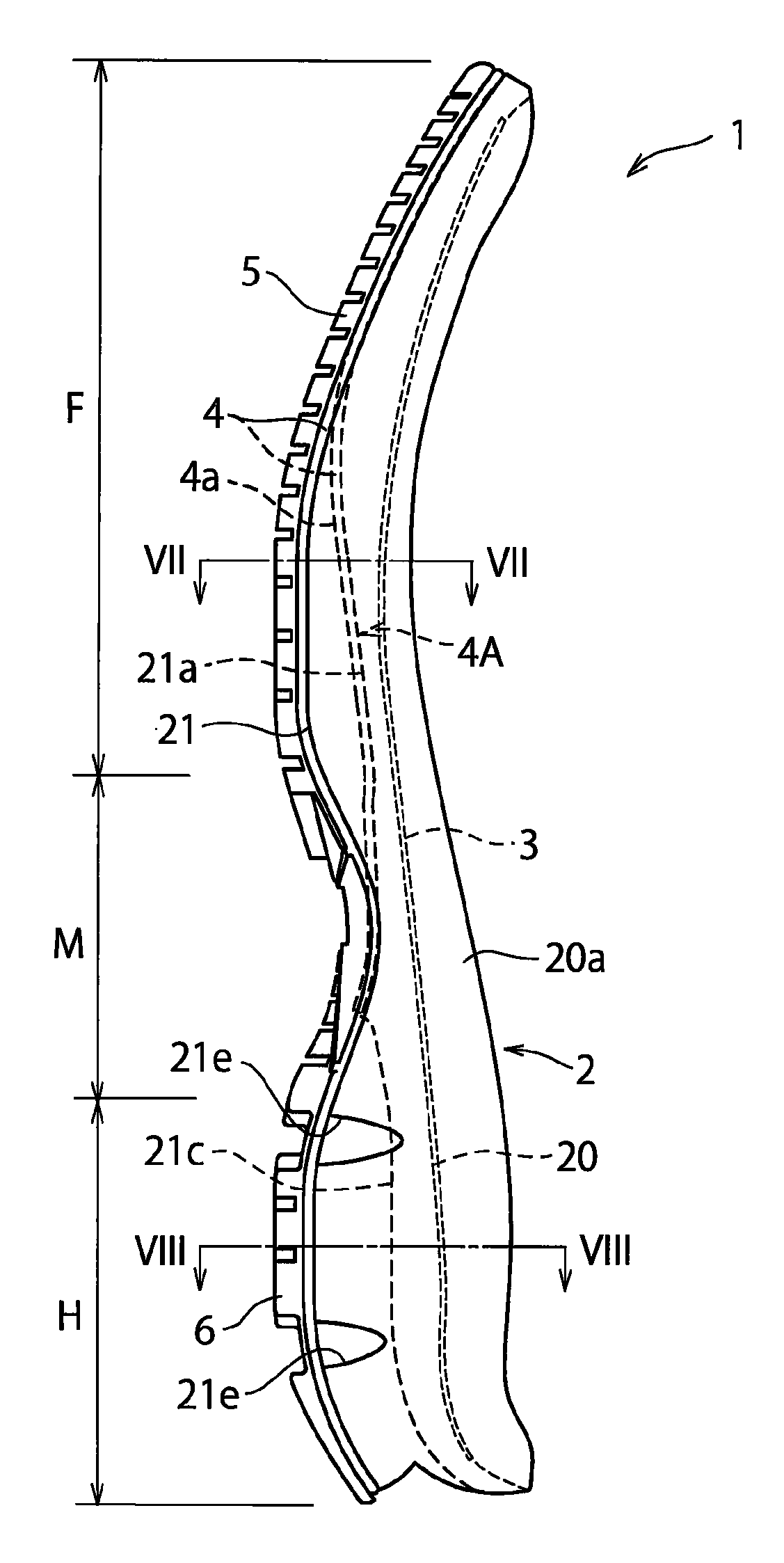
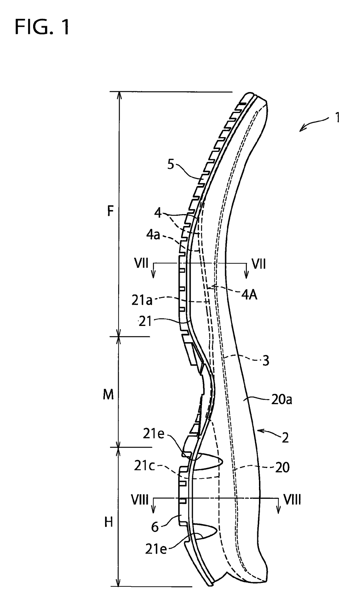
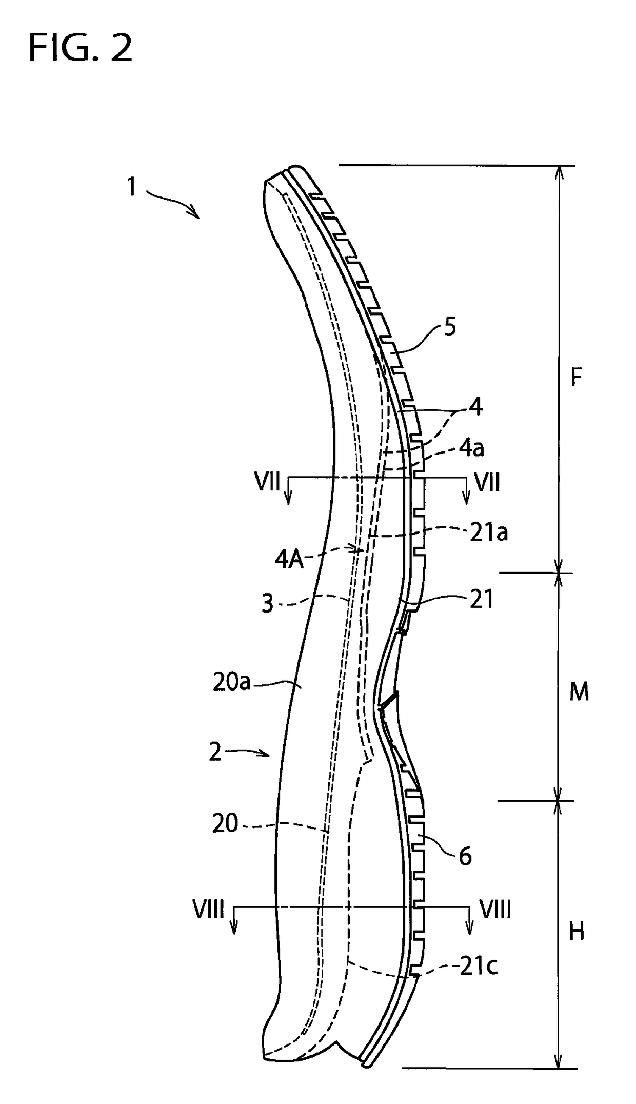
[0051]In the above-mentioned embodiment, an example was shown in which the midsole 2 is disposed along the entire length of the shoe extending from the heel region H through the midfoot region M to the forefoot region F of the shoe, but the sole structure 1 of the present invention has also application to a sole structure in which the midsole 2 is disposed at least at the forefoot region F of the shoe.

second alternative embodiment

[0052]In the above-mentioned embodiment, as a preferred embodiment, an example was shown in which the lower plate 4 has the concave portion 4a corresponding to the hollow portion 21a of the bottom surface 21 of the midsole 2, but in the present invention, the midsole 2 has only to include the hollow portion 21a. For example, the present invention can also be applied to an example in which the lower plate 4 has a flat portion on laterally opposite portions of the forefoot region of the lower plate 4 and has a hole, not a concave portion, on the laterally mid-portion.

third alternative embodiment

[0053]In the above-mentioned embodiment, an example was shown in which the front end of the hollow portion 21a formed in the bottom surface 21 of the midsole 2 extends to a position corresponding to the distal end portions of the third metatarsus MB3 and the fourth metatarsus MB4, but the front end of the hollow portion 21a may extend not only to the distal end portions of the third metatarsus MB3 and the fourth metatarsus MB4 but also to the distal end portion of the second metatarsus MB2. Alternatively, the front end of the hollow portion 21a may extend to the position corresponding to the tip end of the toe of the shoe wearer's foot.


PUM

PropertyMeasurementUnit
heightaaaaaaaaaa
thicknessaaaaaaaaaa
structureaaaaaaaaaa

Abstract

A sole structure for a shoe that can reduce the burden of MP joints and a knee joint of a shoe wearer's foot during running and that can improve cushioning properties. The sole structure of the shoe includes an upper plate of a hard elastic member disposed at a forefoot region of the shoe, a lower plate of a hard elastic member disposed under and spaced away from the upper plate, and a midsole of a soft elastic member interposed between the upper plate and the lower plate. The midsole has a longitudinally extending hollow portion that is upwardly concavely curved at a lateral mid-portion of the midsole. The lower plate has a concave portion corresponding to the hollow portion of the midsole.

Description

FIELD OF THE INVENTION[0001]The present invention relates generally to a sole structure for a shoe, and more particularly, to an improved structure that can reduce the burden of MP joints (i.e. Metatarsophalangeal joints) and a knee joint of a shoe wearer's foot during running and that can improve cushioning properties.BACKGROUND INFORMATION[0002]Japanese patent application publication No. 2010-162318 (hereinafter referred to JP '318) discloses a sole structure for a shoe with a leaf spring structure that is composed of a hard treading plate extending from the heel portion to the forefoot portion and a hard ground-contact plate located away from the treading plate and extending from the heel portion to the forefoot portion and in which the treading plate and the ground-contact plate are coupled to each other at the heel portion (see para. [0010] and FIG. 1). According to the description of JP '318, when an external force to narrow a gap between the treading plate and the ground-cont...

Claims


Application Information

Patent Timeline
Patent Type & Authority Patents(United States)
IPC IPC(8): A43B13/18A43B7/14A43B13/04A43B13/12
CPCA43B13/186A43B7/143A43B13/188A43B13/04A43B13/125A43B7/148A43B13/026A43B13/185
Inventor SATO, NATSUKIODA, TAKAOTAKESHITA, TAKESHIMATSUI, SHOGO
Owner MIZUNO CORPORATION
Why Eureka
Try Eureka