Video display

a technology of video display and video, applied in the field of video display, can solve problems such as user discomfor

Inactive Publication Date: 2005-06-30
SANYO ELECTRIC CO LTD
View PDF2 Cites 7 Cited by
  • Summary
  • Abstract
  • Description
  • Claims
  • Application Information

AI Technical Summary

Benefits of technology

[0008] A video display according to the present invention is characterized by comprising image separation means for restricting a view area in which an image displayed on

Problems solved by technology

However, a user feels inconvenient because he or she ha

Method used


Image

  • Video display
  • Video display
  • Video display

Examples


Embodiment Construction

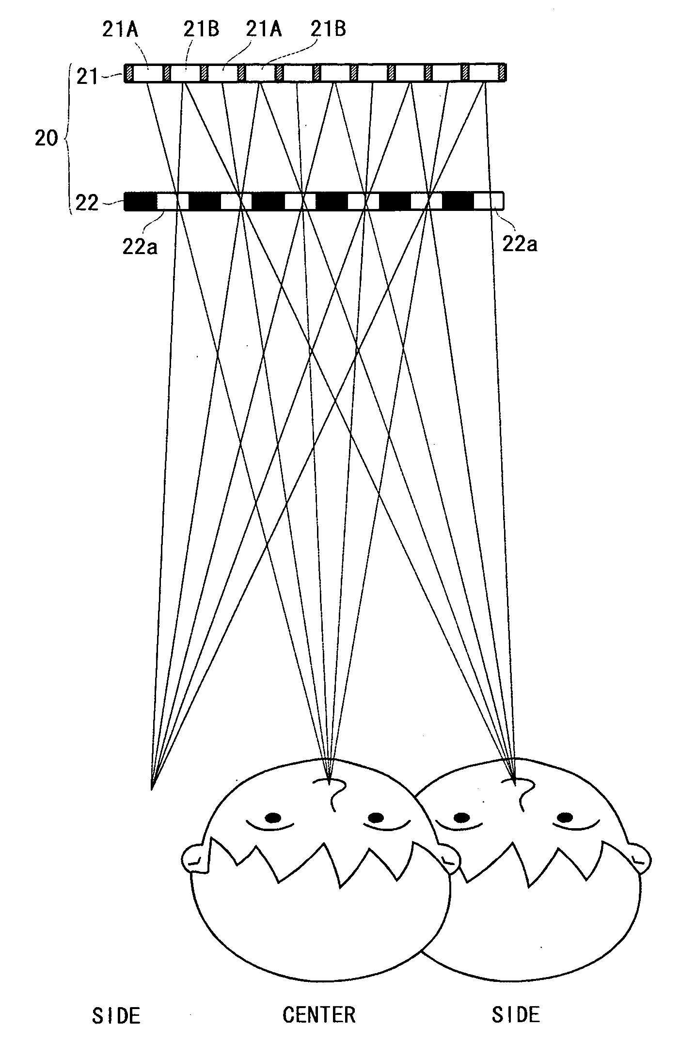
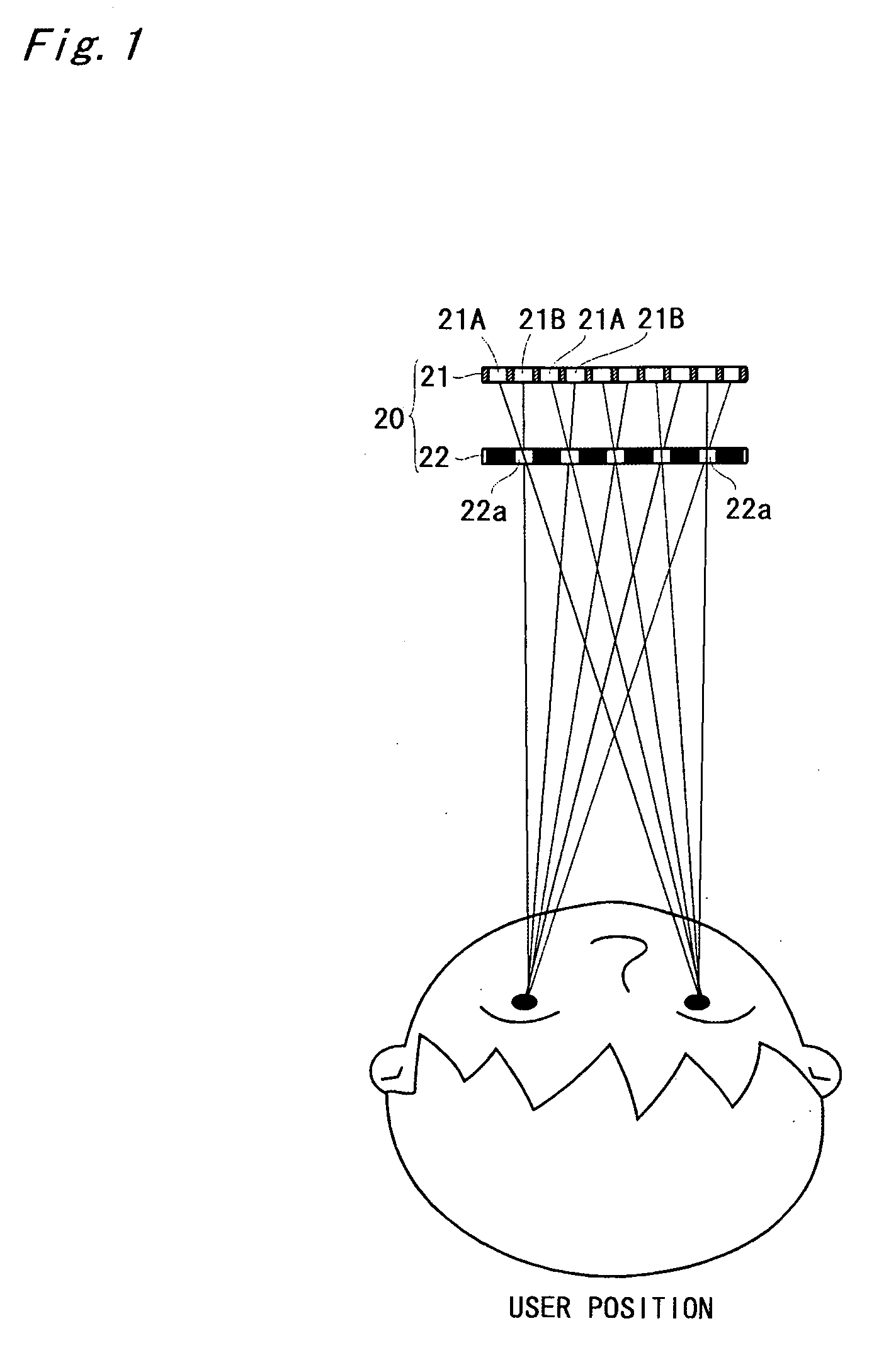
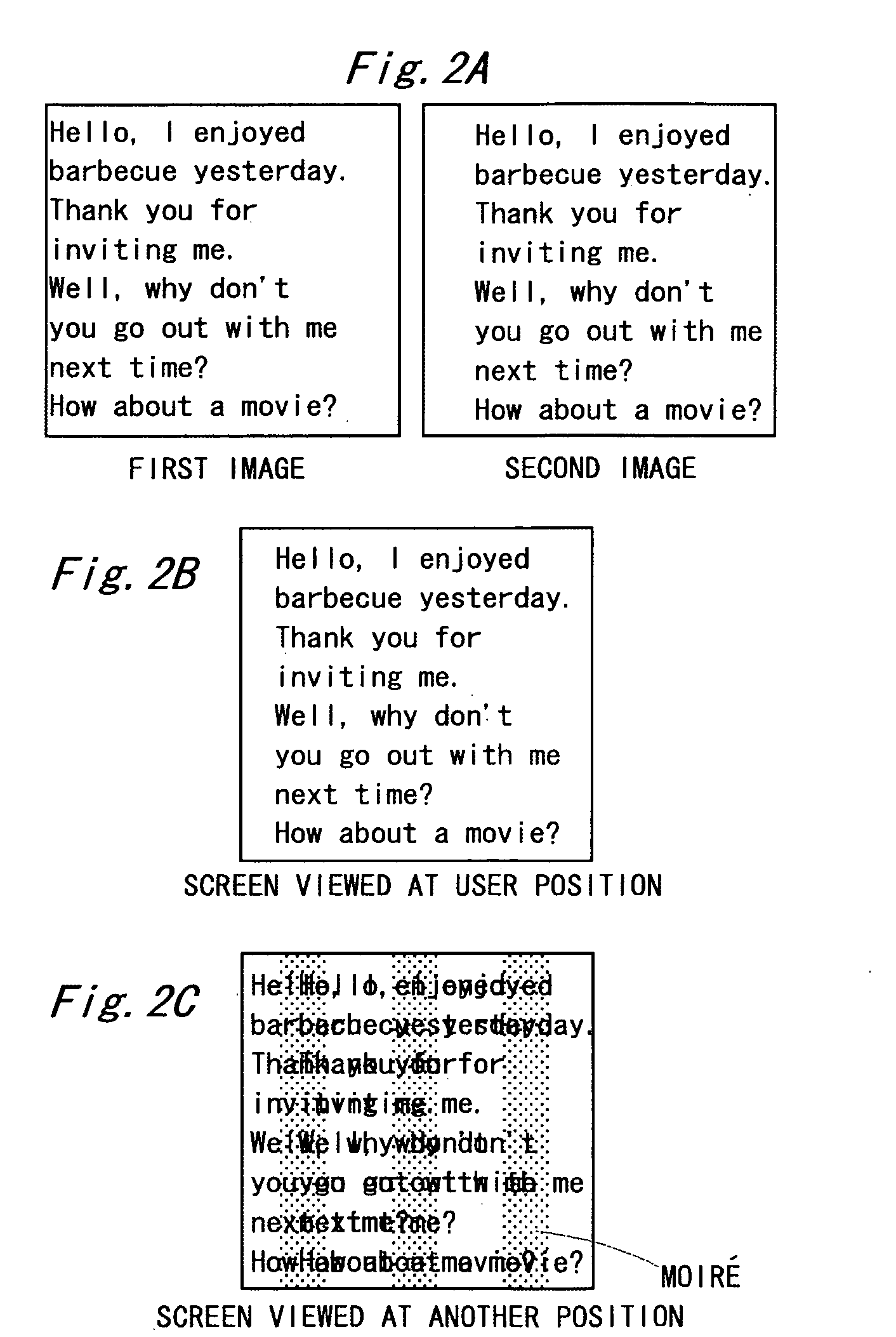
[0020] An embodiment of the present invention will be described on the basis of FIGS. 1 to 8. Although a personal computer comprising a communication environment will be illustrated below, portable equipment such as a portable telephone can be also similarly configured as a video display according to the present invention.

[0021]FIG. 7 illustrates an example of the architecture of a personal computer. A CPU 1 is connected to a north bridge 2 having a system control function and a south bridge 3 having an interface function such as a PCI (Peripheral Component Interconnect) bus or an ISA (Industry Standard Architecture) bus. A memory 4 and a video card 5 through an AGP (Accelerated Graphics Port) are connected to the north bridge 2. A USB (Universal Serial Bus) interface 6, a hard disc drive (HDD) 7, a CD-ROM device 8, and so on are connected to the south bridge 3.

[0022]FIG. 8 illustrates a general video card 5. A VRAM (Video Memory) controller 5b controls writing and reading of draw...


PUM


Abstract

A personal computer monitor comprises a liquid crystal display panel and a liquid crystal barrier. A first image and a second image are respectively drawn on a vertical line and a vertical line in the liquid crystal display panel. The liquid crystal barrier is formed with apertures in a vertically-striped shape. Each of the apertures is formed in correspondence with a set of vertical lines, and is so designed as to introduce the first image to the right eye of a user positioned spaced apart from a screen by a predetermined distance and introduce the second image to the left eye of the user. The first image is an image of a received e-mail, and the second image is an image obtained by subjecting the first image to rightward position shifting processing.

Description

BACKGROUND OF THE INVENTION [0001] Field of the Invention [0002] The present invention relates to a video display equipped with a so-called privacy function for preventing from being taken a peek at the contents displayed on a screen from the side position of the screen. [0003] As a video display equipped with a so-called privacy function, a liquid crystal display using a polarizing thin film which can be arranged at an arbitrary position has been proposed (see JP-A-2001-222004). SUMMARY OF THE INVENTION [0004] However, a user feels inconvenient because he or she has to wear polarizing thin films as glasses, for example. [0005] In view of the foregoing circumstances, an object of the present invention is to provide a video display capable of realizing a so-called privacy function without imposing a burden on a user. [0006] In order to solve above-mentioned problem, a video display according to the present invention is characterized by comprising image separation means for restrictin...

Claims


Application Information

Patent Timeline
IPC IPC(8): G02B27/00G02B27/02G02B27/22G02F1/1335G02F1/1347G09F9/00G09F19/14H04N13/00
CPCG02B27/2214G02F1/133524H04N13/0409G02F2001/133562G02F1/1347H04N13/31G02F1/133562H04N13/00G02B27/00G02F1/1335G02B30/27
Inventor MASHITANI, KEN
Owner SANYO ELECTRIC CO LTD
Why Eureka
Try Eureka