Air bath

Inactive Publication Date: 2005-08-11
KOHLER CO
View PDF12 Cites 8 Cited by
  • Summary
  • Abstract
  • Description
  • Claims
  • Application Information

AI Technical Summary

Benefits of technology

[0013] A control interface allows the user to quickly and easily adjust the air to one or more zones by the press of a button. The control can also

Problems solved by technology

Thus, while providing targeted massage, this tub maybe somewhat ineffective for full-body therapy.
Moreover, the delivery system is very complex and requires several flexible conduits, one for each jet.
Air distributi

Method used


Image

  • Air bath
  • Air bath
  • Air bath

Examples


Example

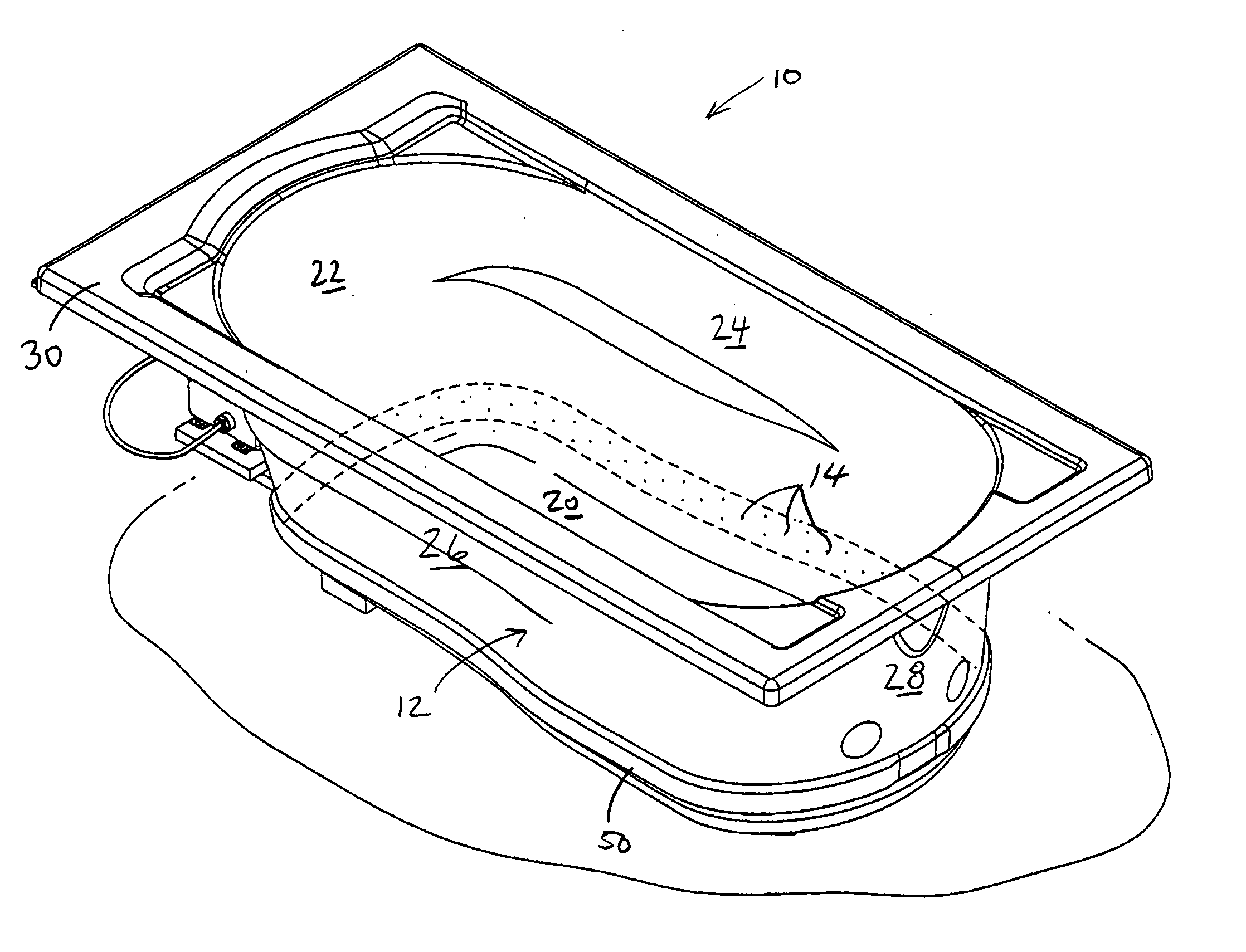
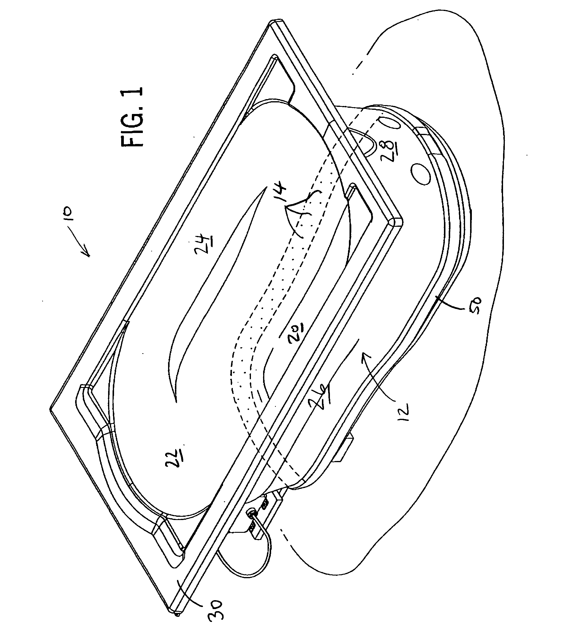
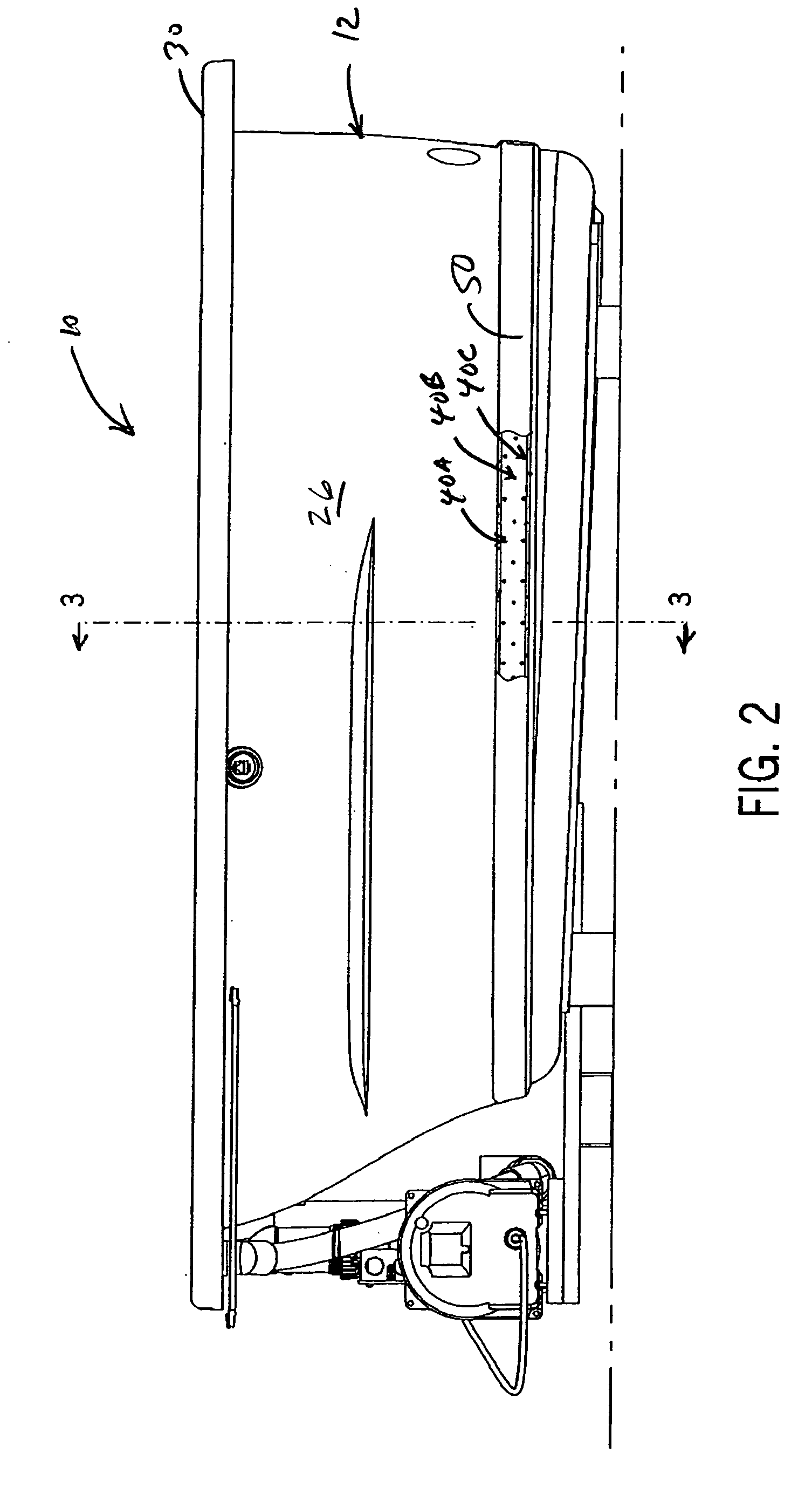
[0024] The present invention provides an air bath 10. FIGS. 1-7 illustrate the configuration of its basin 12 as well as the arrangement of air jets 14. FIG. 8 illustrates schematically the air delivery system that can be used with the basin of FIGS. 1-7 as well as the basin 12′ shown in FIG. 8. The difference between the two basins is that the basin 12′ is specially configured, as will be described, to provide selective control of air flow to prescribed zones, for example, head, lumbar, and foot zones. FIG. 8 also illustrates that the air bath can include a chromatherapy system 18 to illuminate the bath water various colors. A suitable chromatherapy system is disclosed in U.S. Pat. No. 6,360,380 and application Ser. No. 10 / 068,395, filed Feb. 6, 2002, both assigned to the assignee of the present invention and hereby incorporated by reference as though fully set forth herein. Also, in any case, the tub basin can be configured as a conventional bathtub, whirlpool, spa or swimming pool...


PUM


Abstract

An air bath has air jets arranged in rows extending around the side walls of the water basin. The rows of air jets are spaced vertically so that they are at different heights within the basin and so that air jets in the higher row(s) realize less pressure from the water in the basin. Air is delivered to the air jets through a ring-like air manifold formed of a single channel or multiple channels, the latter allowing for air flow control to different zones of the tub.

Description

CROSS-REFERENCE TO RELATED APPLICATIONS [0001] Not applicable. STATEMENT OF FEDERALLY SPONSORED RESEARCH OR DEVELOPMENT [0002] Not applicable. BACKGROUND OF THE INVENTION [0003] The present invention relates to tubs such as bathtubs in which air is bubbled into the water to create a hydrotherapy action. [0004] Therapeutic water baths and pools are well-known. Spas or whirlpool tubs are common examples in which water streams from jets through the walls of the basin flow into the water beneath the surface, usually directed at large muscle areas of a person's body, for example shoulders, back and thighs. The force from the jets “massage” the bather directly as well as agitate the water to provide therapeutic effects for other parts of the body not directly in the path of the jets. U.S. Pat. No. 6,185,757 discloses one such bath with water jets. [0005] Although water jets are common, some tubs use air streams to agitate the water. For example, U.S. Pat. No. 5,898,958 discloses one tub t...

Claims


Application Information

Patent Timeline
IPC IPC(8): A61H33/06
CPCA61H33/026A61H33/028A61H2033/0058A61N2005/0663A61H33/60A61H2201/10
Inventor SWART, PETER W.DAIKUBARA, MIKE YOSHIAKIWANG, DIANA
Owner KOHLER CO
Why Eureka
Try Eureka