
Nail clippers

a nail clipper and clipper technology, applied in the field of nail clippers, can solve the problems of not providing protection from the cutting blades for the skin, and enhancing cutting performance, and achieve the effect of preventing skin and tissue injury, particularly effective at cutting ingrown nails

Inactive Publication Date: 2005-08-11
HARTLEY WAYNE
View PDF9 Cites 4 Cited by
  • Summary
  • Abstract
  • Description
  • Claims
  • Application Information

AI Technical Summary

Benefits of technology

[0004] The present invention is nail clippers that assist in preventing injury to the skin and tissue that surround the fingernails and toenails to be cut. The nail clippers are particularly efficacious at cutting ingrown nails.

Problems solved by technology

In nail clippers known and used in the prior art, the clippers do not provide protection from the cutting blades for skin that is in close proximity to the nail to be cut.
Further, in prior art nail clippers, there is no provision for enhancing cutting performance where ingrown nails, and particularly toenails, are involved.

Method used


Image

  • Nail clippers
  • Nail clippers
  • Nail clippers

Examples


Embodiment Construction

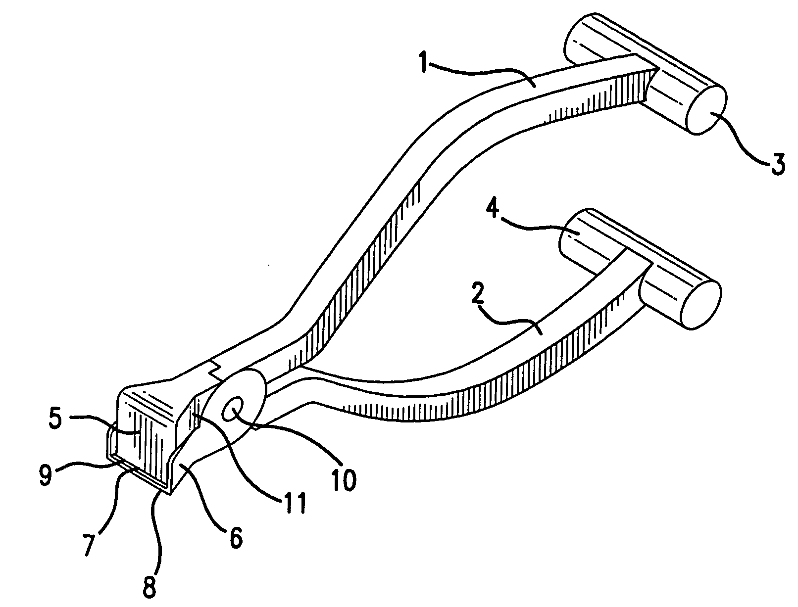
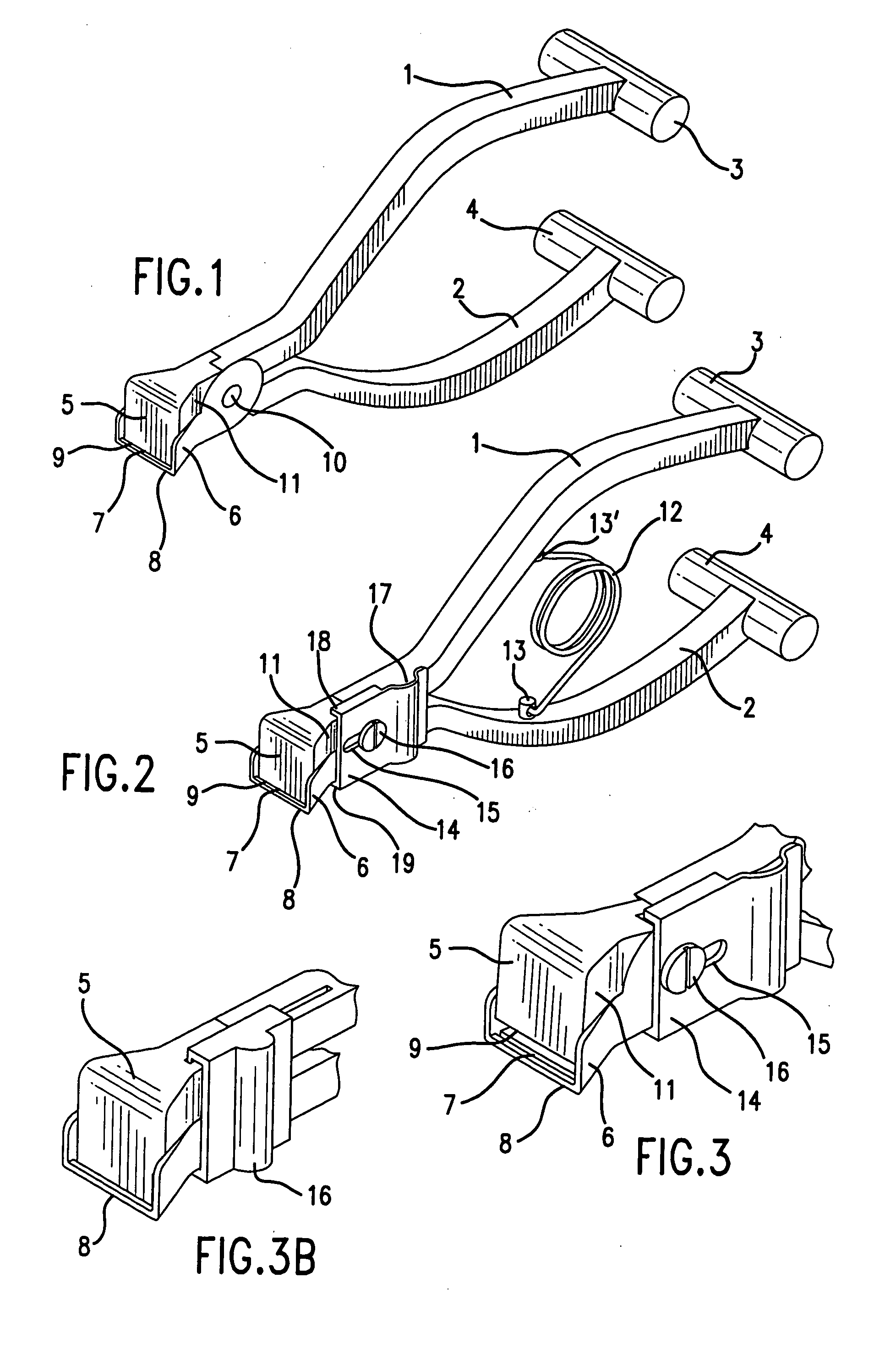
[0021] Turning now to the drawing figures, an embodiment of the present invention is shown in FIG. 1. The nail clippers comprise an upper handle 1 and a lower handle 2. A grip 3 may be provided for the upper handle, and a grip 4 may be provided for the lower handle. An upper blade 5 communicates with the upper handle. A lower tray 8 communicates with the lower handle.

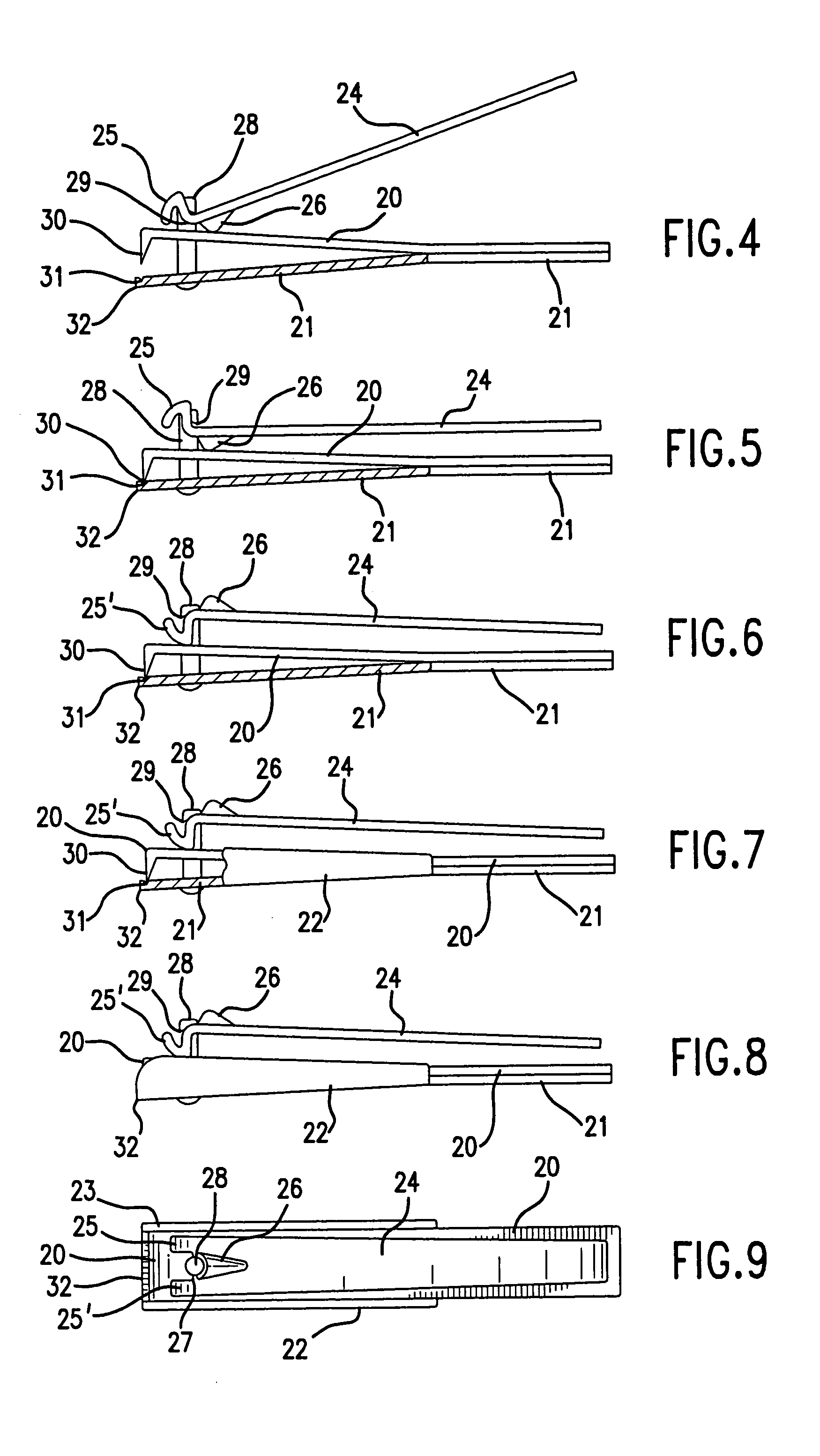
[0022] The lower tray has a front portion which extends beyond the upper blade when the upper blade is displaced to contact the lower tray. The upper blade is sharpened on a lower edge 9, which contacts the lower tray 8. Side dams 6 extend from each side of the lower tray. The upper blade is positioned fully within each side dam and above the lower tray. A groove or slot 7 may be formed in the lower tray to receive the upper blade.

[0023] Each side dam extends outwardly and beyond the tray as shown in the drawing figures. Each of the side dams extends outwardly and beyond the upper blade, when the blade is closed again...


PUM


Abstract

Nail clippers have a lower tray and side dams which extend upwardly from either side of the lower tray. A nail to be cut is positioned between the lower tray and an upper blade. The upper blade is displaced toward the lower tray, and within the side dams, until the upper blade contacts the lower tray, passing through the nail to cut the nail. A front portion of the lower tray extends outwardly and beyond the upper blade when the upper blade is closed against the tray. The nail clippers are structured to prevent injury to the skin and tissue that surrounds the fingernails and toenails to be cut. The nail clippers are particularly efficacious at cutting ingrown nails.

Description

FIELD OF THE INVENTION [0001] This invention relates to nail clippers. BACKGROUND OF THE INVENTION [0002] Nail clippers are known and used in the art. Nail clippers are used to trim fingernails and toenails of humans and other animals. Nail clippers as most commonly known and used in the art have an upper blade and a lower blade, which are substantially identical in architecture. The upper blade and lower blade are displaced towards each other, with the nail to be cut positioned between the blades. The blades are displaced towards each other until contact is made with the nail, and displacement is continued until the nail is divided by the blades, and the blades contact each other. [0003] In nail clippers known and used in the prior art, the clippers do not provide protection from the cutting blades for skin that is in close proximity to the nail to be cut. Further, in prior art nail clippers, there is no provision for enhancing cutting performance where ingrown nails, and particula...

Claims


Application Information

Patent Timeline
Patent Type & Authority Applications(United States)
IPC IPC(8): A45D29/02
CPCA45D29/02
Inventor HARTLEY, WAYNE
Owner HARTLEY WAYNE
Learn More