
Vehicle mirror having polymeric reflective film element and self-dimming element

a reflective film and mirror element technology, applied in the field of rearview mirrors, can solve the problems of increasing the risk of costly repairs or replacements, increasing the cost of fabrication and assembly process, and affecting the quality of the mirror element,

Inactive Publication Date: 2005-08-11
MAGNA DONNELLY MIRRORS NORTH AMERICA LLC
View PDF38 Cites 38 Cited by
  • Summary
  • Abstract
  • Description
  • Claims
  • Application Information

AI Technical Summary

Benefits of technology

"The invention is a vehicular mirror system that includes a reflective element mounted on a vehicle and a mounting plate for mounting the reflective element. The mounting plate has a chromomorphic polymer element that can change from a first state to a second state. The chromomorphic polymer element is transparent in the first state and has a translucent color in the second state. The system also includes a controller for activating the chromomorphic polymer element and a heating element that can defrost or defog the reflective element. The system provides a reflection image that is free of visible distortion and can include a transparent element for protection of the chromomorphic polymer element. The invention also includes a method for activating the chromomorphic polymer element and a method for protecting the reflective element from weather and impact forces."

Problems solved by technology

Manufacture of multi-piece mirror elements involves several separate fabrication and assembly steps, and the complicated fabrication and assembly process can be expensive.
Having a mirror with multiple pieces increases the likelihood that one piece may fail or be damaged, thereby increasing the risk that costly repairs or replacement will be necessary.
Furthermore, the differential shrinkage rates between the mounting plate and the glass require a design “gap” between these elements to avoid cold weather creating excessive side pressure and hoop stress that may distort and ultimately crack the glass element.
The various components making up the mirror element can be relatively heavy, particularly where several pieces of glass are used.
In particular, mms used for trucks, SUVs, and other large vehicles can be quite large and heavy.
Heating elements for defogging or defrosting the mirror must be larger and will consume more energy due to the higher heat capacity of the heavy, multi-piece mirror element.
The use of a plastic mounting panel can give rise to structural imperfections such as “read-through” and waviness which can, in turn, introduce unacceptable optical imperfections in the mirror element.
Surfaces with high curvature hide these flaws, but they can be quite noticeable on flat surfaces.
Similarly, deviations from a plane surface, or “waviness,” in the plastic mounting panel can give rise to a non-planar reflective surface, particularly where a reflective film is used, thereby distorting the reflection image.
This generally comprises a separate glass or plastic component, further increasing the fabrication costs and weight of the mirror assembly.
Locating the lights behind the glass will reduce the intensity of the lights due to transmission losses as the light shines through the glass.
To compensate, larger, heavier lights having an increased power consumption are necessary.
These types of electrochromic mirror elements are typically expensive to manufacture and install.
In addition, the gel must be sealed within the glass plates, causing additional expense and repair if the seal fails during use.
Further, the glass plates can provide an undesirable amount of weight to a typical rearview mirror assembly since they require a pair of glass plates as well as the remainder of the electrochromic element.
Finally, the electrochromic gel is caustic, can be dangerous to handle during manufacture, and users risk exposure to the electrochromic material as a result of its corrosive nature.

Method used


Image

  • Vehicle mirror having polymeric reflective film element and self-dimming element
  • Vehicle mirror having polymeric reflective film element and self-dimming element
  • Vehicle mirror having polymeric reflective film element and self-dimming element

Examples


first embodiment

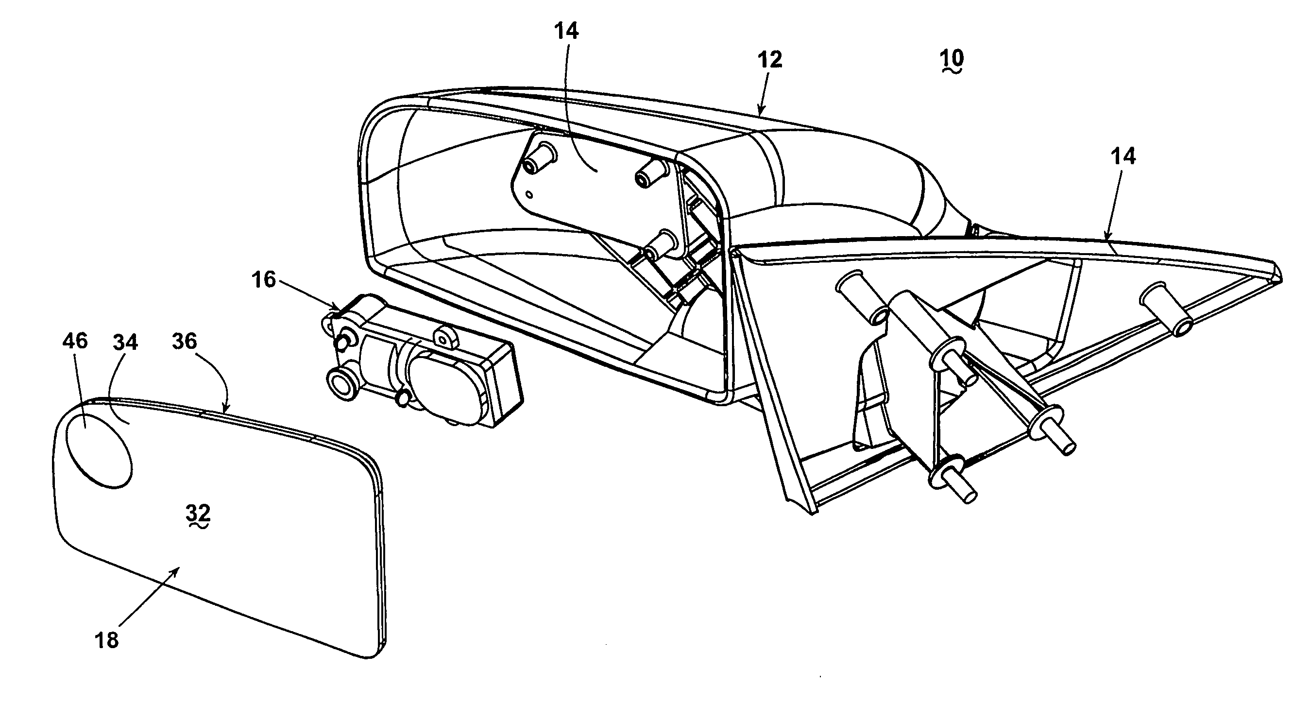
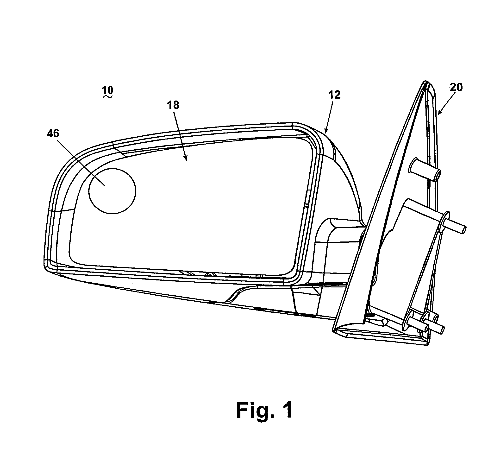
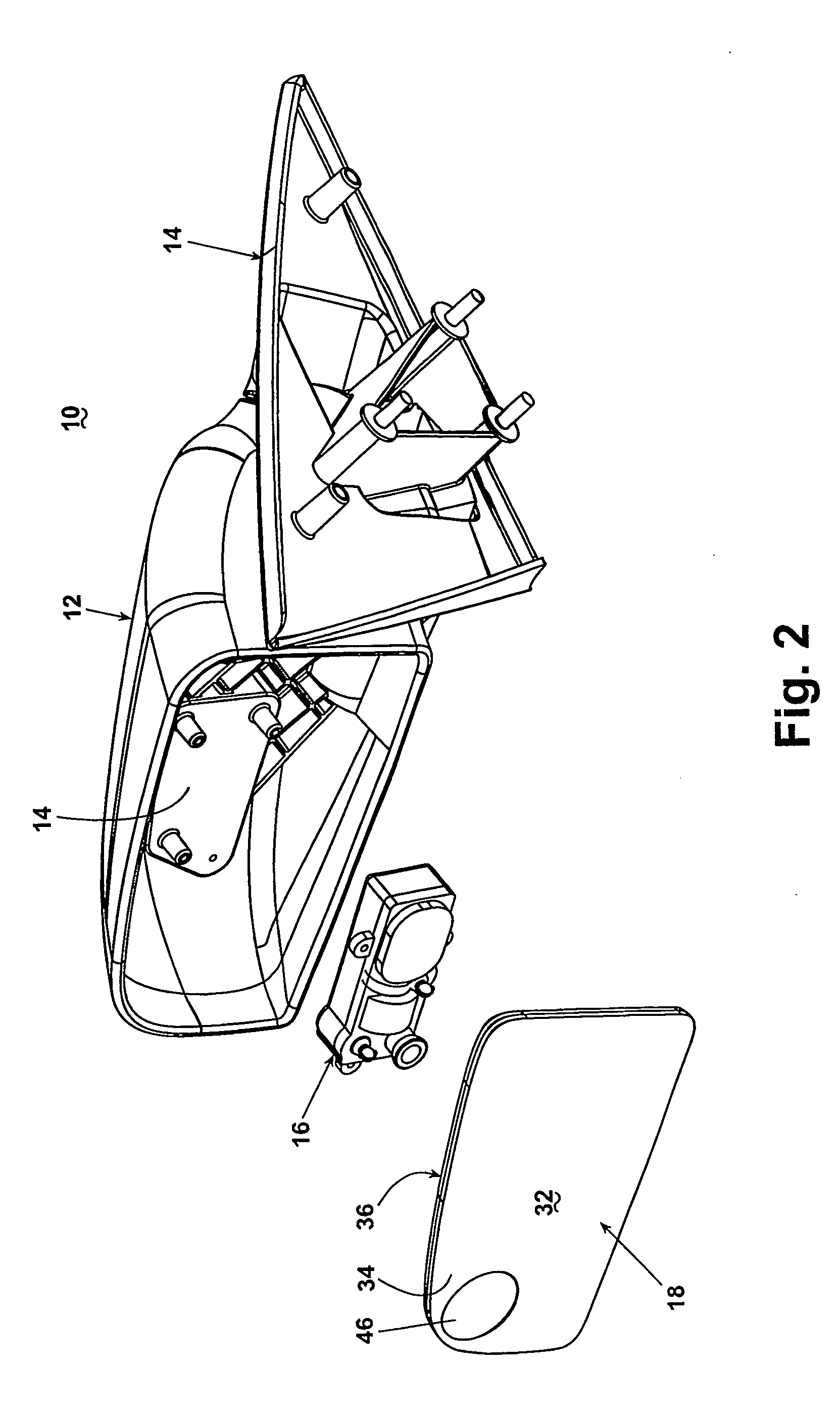
[0061] A coated plate mirror assembly 10 according to the invention is shown in FIGS. 1 and 2. The mirror assembly 10 comprises a housing assembly 12 enclosing a generally conventional mounting bracket assembly 14, a generally conventional adjustment assembly 16 (shown as a tilt actuator assembly), a reflective element 18, and a base assembly 20 for attaching the mirror assembly 10 to a motor vehicle (not shown). The housing assembly 12 is a generally conventional rearview mirror housing assembly for an automotive vehicle. The mounting bracket assembly 14 mounts the adjustment assembly 16 which, in turn, mounts the reflective element 18. The adjustment assembly 16 controls the vertical and horizontal sight adjustment of the reflective element 18. Although a single adjustment assembly is shown, multiple adjustment assemblies can be utilized, each adjustment assembly controlling a single specific function, such as horizontal axis and vertical axis adjustment. It will also be understoo...

second embodiment

[0071] Referring to FIGS. 7-9, the rearview mirror assembly is shown comprising a light assembly 70 comprising a plurality of lighting elements 72 in a frame 74, shown for purposes of illustration as arranged in a generally semicircular configuration. The lighting elements 72 are adapted to lie along the circumference of the convex surface 46, which will highlight and draw the driver's attention to the convex surface 46. The use of the reflective film 32 provides a plurality of individual reflective surfaces for the lighting elements 72 for magnifying the intensity of the light therefrom. These reflective surfaces are readily fabricated through the use of the film 32.

[0072] The lighting elements 72, such as small light bulbs or light-emitting diodes, are operably interconnected to the vehicle's 12-volt DC electrical supply and control systems for selective operation of the light assembly 70. As an example, the light assembly 70 can be electrically interconnected with the vehicle's t...

third embodiment

[0077] Turning now to FIGS. 10-13, the mirror assembly 10 is shown having several of the previously-described elements and additionally comprising a mounting plate 114, a first glass element 116, a second glass element 118, and a chromomorphic, i.e. color-changing, polymeric element 120. Thus, like numerals will be used to identify like elements.

[0078] It will be understood that, while a mirror assembly 10 suitable for attachment to an exterior portion of a vehicle, such as in a door-mounted rear view external mirror, is shown and described herein, the invention is equally applicable to an interior windshield-mounted mirror assembly without departing from the scope of the invention.

[0079] As shown in FIGS. 10-13, the mirror assembly 10 preferably comprises a mirror housing 122 mounted to a base 124. The mirror assembly 10 can also include an actuator 126 preferably provided for accomplishing typical pitch-and-roll adjustment of the mirror components 114-120 as is known in the a it....


PUM


Abstract

A rearview mirror assembly comprises a reflective element, preferably fabricated of a lightweight, rigid, high-strength plastic and a relatively thin reflective film conformably attached thereto. A portion of the reflective element can also comprise a convex surface for monitoring the “blind spot” typically experienced by the driver. A mirror-mounted light assembly, such as for turn signals, can be incorporated into the reflective element. The mirror assembly can also comprise a chromomorphic polymeric element in planar alignment with the reflective element, which can be electrically and / or thermally activated. The chromomorphic polymeric element can change its resident color between transparent and a predetermined activated color to provide a dimming function as a characteristic of the particular chromomorphic polymeric element that is employed.

Description

CROSS-REFERENCE TO RELATED APPLICATION [0001] This application claims the benefit of U.S. provisional application Ser. No. 60 / 319,199, filed Apr. 23, 2002, and 60 / 319,218, filed May 1, 2002, which are incorporated herein in their entirety.BACKGROUND OF THE INVENTION [0002] 1. Field of the Invention [0003] The invention relates to a rearview mirror for an automotive vehicle. In one aspect, the invention relates to a one-piece mirror element for a rearview mirror. In another aspect, the invention relates to a one-piece mirror element having an integral convex portion. In another aspect, the rearview mirror has an automatic dimming feature performed by a chromomorphic polymer. [0004] 2. Description of the Related Art [0005] Side-mounted rearview mirrors for automotive vehicles typically comprise a multi-piece (and multi-layer) mirror element. The mirror element will generally comprise a mounting panel or “glass case” to which a reflective element is attached. The glass case can be fabr...

Claims


Application Information

Patent Timeline
Patent Type & Authority Applications(United States)
IPC IPC(8): B60Q1/26B60R1/08B60R1/12
CPCB60Q1/2665B60R1/1207B60R1/088B60R1/082
Inventor BODDY, IANFOOTE, KEITH D.RUSE, JAMES A.
Owner MAGNA DONNELLY MIRRORS NORTH AMERICA LLC
Learn More