Compressor system with movable seal lands

a compressor system and seal technology, applied in the direction of machines/engines, stators, liquid fuel engines, etc., can solve the problems of extended outages and hardware replacement, seal clearances are approached, and performance degradation

Active Publication Date: 2005-08-11
SIEMENS ENERGY INC
View PDF0 Cites 16 Cited by
  • Summary
  • Abstract
  • Description
  • Claims
  • Application Information

AI Technical Summary

Benefits of technology

[0018] A turbine engine with such a compressor section is operated such that the compressor rotor turns at about 2300 rpms to about 3600 rpms. The rotational forces generated by the turning rotor can be used to move at least the second end of the seal land radially outward from the first position so as to reduce but not completely close the gap. In one embodiment, the second end of the seal land can be fully radially outwardly extended at about 3600 rpms.

Problems solved by technology

The compressed fluid will naturally seek the path of least resistance, that is, the lower pressure upstream side of the stationary airfoil, which can result in reverse axial flow through the compressor, thereby degrading performance.
Seal rubbing during off design conditions has been known to cause the seals to liberate, wrap around the neighboring stationary airfoils, and ultimately cut through the stationary airfoils, resulting in extended outages and hardware replacement.
In the past, the problem of seal clearances has been approached by providing large seal clearances during non-standard engine conditions where the seal clearances would otherwise be expected to be the smallest because of thermal inequalities and other factors.
However, because the minimum seal clearances are sized for these off design conditions, the seal clearances become overly large when the engine achieves full speed (i.e. normal operation).
Consequently, the compressor / engine experiences measurable performance decreases in power and efficiency due to clearance leakage at normal operation.

Method used


Image

  • Compressor system with movable seal lands
  • Compressor system with movable seal lands
  • Compressor system with movable seal lands

Examples


Embodiment Construction

[0023] Aspects of the present invention improve upon prior compressor systems used in connection with turbine engines. Aspects of the present invention relate to a compressor system having movable seal lands that permit relatively large clearances during non-normal operating conditions and relatively minimal clearances during normal operation of the engine, thereby enhancing the performance of the compressor / engine.

[0024] Embodiments of the invention will be explained in the context of one possible compressor system, but the detailed description is intended only as exemplary. Embodiments of the invention are shown in FIGS. 1-4, but the present invention is not limited to the illustrated structure or application.

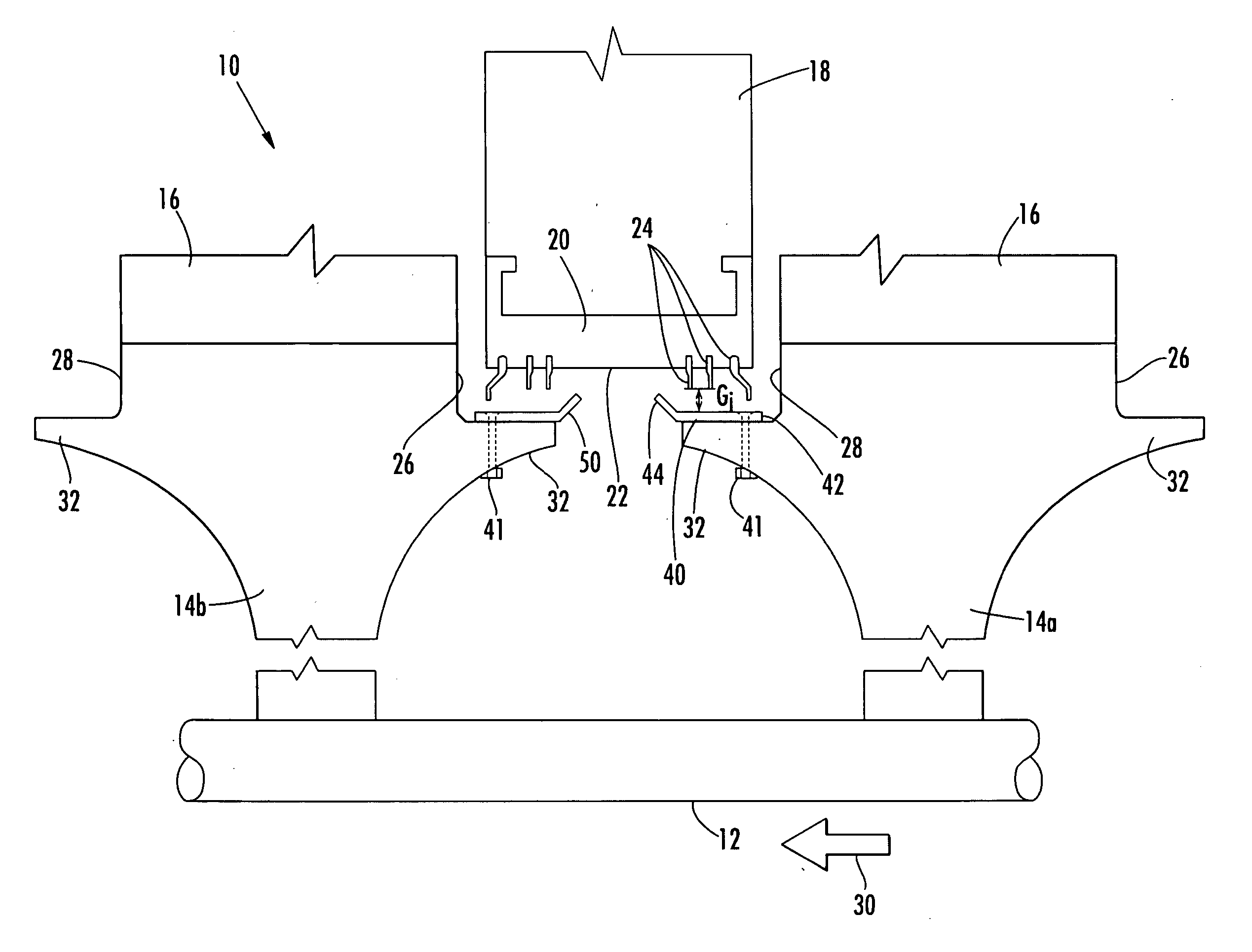
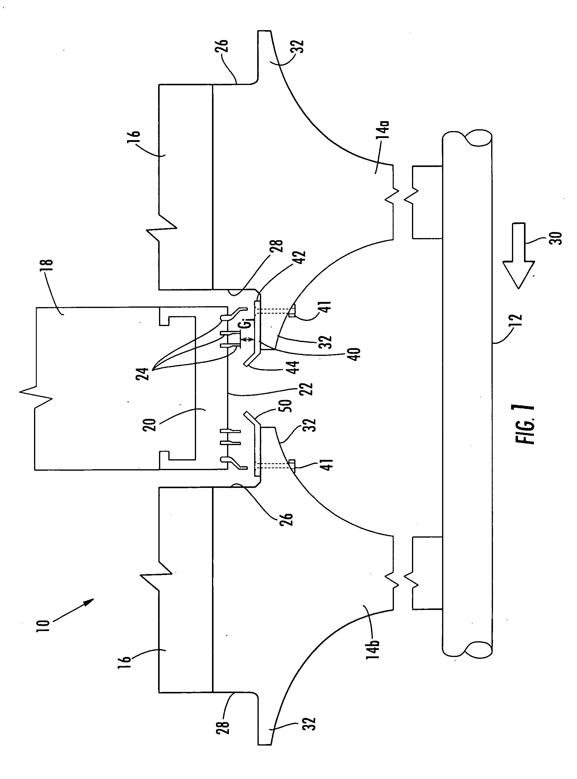
[0025]FIG. 1 shows an embodiment of a compressor system 10 according to aspects of the invention. The compressor 10 includes a rotatable shaft or rotor 12 on which one or more disks 14a, 14b (collectively referred to herein as 14) are secured as is known in the art. Each of...


PUM


Abstract

Aspects of the invention relate to a compressor system for a turbine engine that not only provides large compressor seal clearances as the engine passes through non-standard operating conditions, but also minimizes the clearances during normal engine operation, thereby increasing the efficiency of the compressor. In one embodiment, a substantially annular seal land is secured at one end to an annular extension arm on a compressor disk. When the engine reaches steady state operation, the non-attached end of the seal land can extend radially outward to reduce the clearance between the seal land and a shroud extending over the ends of the adjacent stationary airfoils. The seal land can be designed to resist the rotational forces imparted by the turning rotor until a certain desired operating condition is reached. In one embodiment, the seal land reaches full extension when the engine is operating at about 3600 rpm.

Description

FIELD OF THE INVENTION [0001] The invention relates in general to turbine engines and, more particularly, to a system and method for increasing the efficiency of the compressor section of a turbine engine. BACKGROUND OF THE INVENTION [0002] The compressor section of a turbine engine can comprise several rows of airfoils, alternating between rows of rotating airfoils and rows of stationary airfoils. Each row of rotating airfoils comprises a plurality of airfoils held on a disk which is, in turn, attached to a rotor. Thus, the attached airfoils rotate along with the rotor. Each row of stationary airfoils comprises a plurality of stationary airfoils affixed at one end to the inner periphery of a ring or other airfoil carrier such as a diaphragm pack. The stationary airfoils extend radially inward from the airfoil carrier, terminating at an inner shroud. [0003] The general operation of a compressor is well known in the art—the rotating airfoils force a fluid axially through the compress...

Claims


Application Information

Patent Timeline
Patent Type & Authority Applications(United States)
IPC IPC(8): F01D11/00F01D11/02F04D29/08F16J15/16F16J15/447
CPCF01D11/001F01D11/025F16J15/4472F16J15/164F04D29/083
Inventor GARNER, CHAD MARCUS
Owner SIEMENS ENERGY INC
Why Eureka
Try Eureka