Muscle powered dynamic knee brace

a knee brace and dynamic technology, applied in the field of orthopaedic knee braces, can solve the problems of increasing the pressure on the damaged compartment, increasing the pain of patients' activities, and providing a static bending force across the kn

Inactive Publication Date: 2005-08-11
BREG
View PDF16 Cites 26 Cited by
  • Summary
  • Abstract
  • Description
  • Claims
  • Application Information

AI Technical Summary

Benefits of technology

[0010] A dynamic knee brace that can be used to apply a bending force across the knee. Two brace arms are connected by a central joint that allows the knee to pivot. A joint in each brace arm allows the brace arm to be inclined in the medial / lateral plane. A cam assembly actively and dynamically inclines each brace arms toward the leg as the knee moves from flexion to full extension. An adjustment mechanism for the cam assemblies provides control over the timing of the dynamic force and thus the maximum amount of inclination each brace arm achieves at full extension. Preferably, the adjustment mechanism adjusts the cams equally so that both brace arms are inclined by the same amount, regardless of the adjustment used.

Problems solved by technology

This damage to the compartment on one side of the knee causes increased pressure on the damaged compartment, which may be severe enough to be visible as a change in the angulation of the joint.
This makes it painful for the patient to engage in activities where there is a load being applied to the knee, such as waking or even standing.
A major disadvantage of most braces for treating unicompartmental osteoarthritis is that they provide a static bending force across the knee, which does not change as the knee moves between flexed and extended positions.
The pressure in the damaged compartment increases, thereby causing pain, only when weight is being applied to the leg.
The application of force when the knee is partially flexed can make the brace uncomfortable to wear.
In addition, when the knee is partially flexed applying a bending force across the knee results in a rotational force that results in a tendency of the brace to rotate around the leg, which lessens its effectiveness.

Method used


Image

  • Muscle powered dynamic knee brace
  • Muscle powered dynamic knee brace
  • Muscle powered dynamic knee brace

Examples


Embodiment Construction

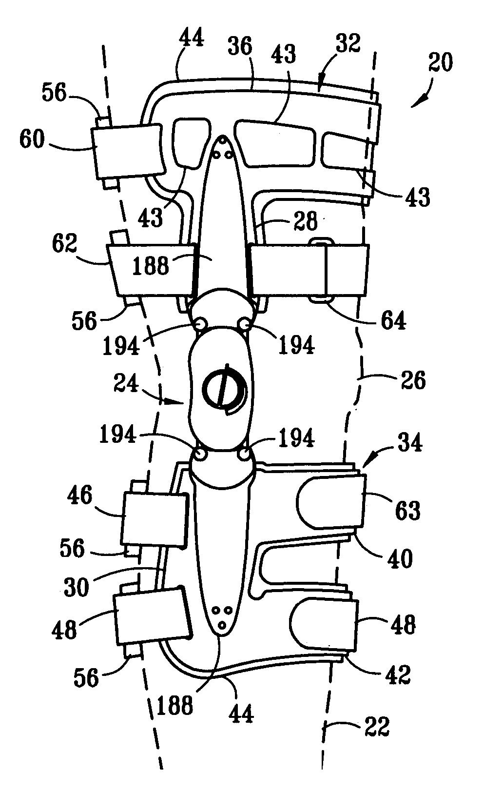
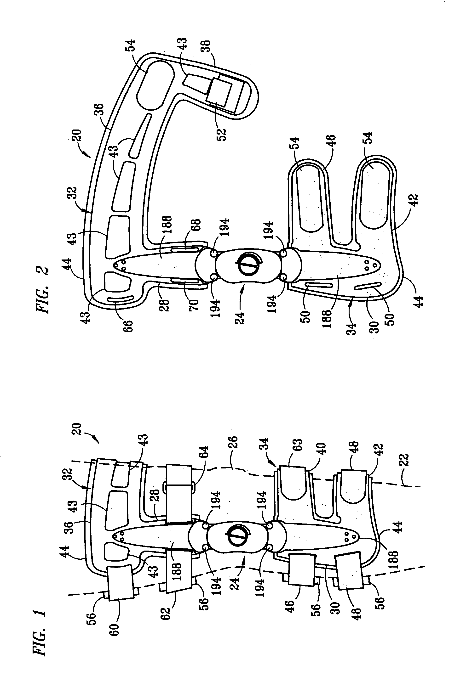
[0027] A brace according to a preferred embodiment of the present invention is adapted to be secured around the leg of a patient, use muscle power to provide the required amount of bending force across the knee as the knee moves to full extension, and to dynamically remove the force as the knee flexes. While the following description of the preferred embodiment relates to a brace for treating the medial compartment of the left leg, one of skill in the art would understand any minor alterations required to adapt the preferred embodiment of the current invention for the treatment of the medial or lateral compartment of either knee.

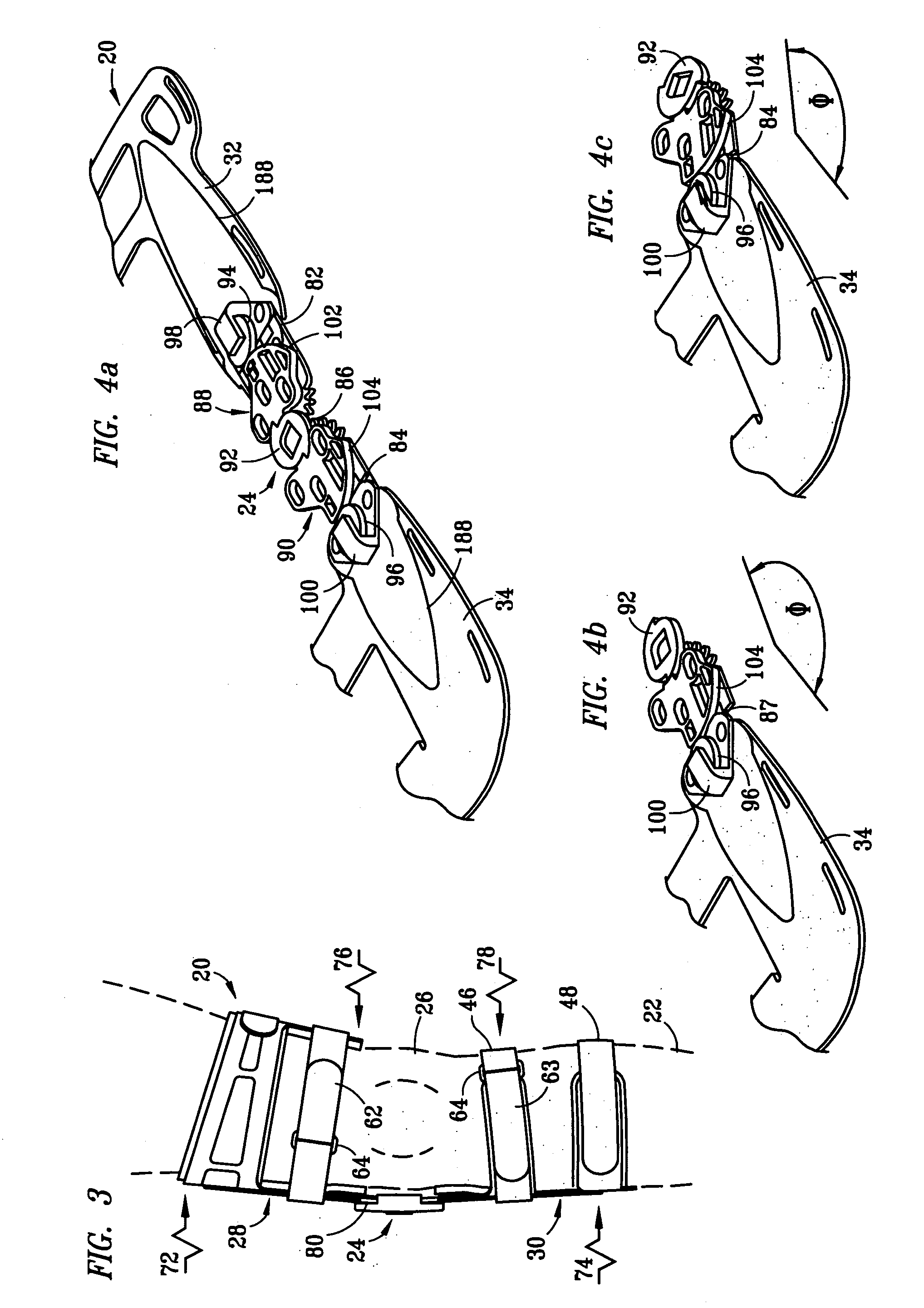
[0028] With respect to FIGS. 1 and 2, brace 20 is adapted to be located about leg 22 such that joint 24 is next to the compartment of knee 26 that is damaged and needs to be opened. Upper shell 32 is located against leg 22 above knee 26 and lower shell 34 is located against leg 22 below knee 26. Upper shell 32 is secured to media / lateral joint 82 through th...


PUM


Abstract

A dynamic knee brace that can be used to apply a bending force across the knee. Two brace arms are connected together by a central joint that allows the knee to pivot. A joint in each brace arm allows the brace arm to be inclined toward the leg. A cam assembly is present to actively incline each brace arms toward the leg as the knee moves to full extension. An adjustment mechanism for the cam assemblies provides control over the maximum amount of inclination each brace arm achieves. Preferably, the adjustment mechanism adjusts the cams equally so that both brace arms are inclined by the same amount.

Description

BACKGROUND OF THE INVENTION [0001] 1. Field of the Invention [0002] This invention relates generally to orthopedic knee braces and, more particularly, to a dynamic knee brace that uses muscle power to apply a bending force across a knee. [0003] 2. Description of Related Art [0004] Unicompartmental osteoarthritis is a condition where the cartilage on one compartment of the knee has worn away more than the other compartment. This damage to the compartment on one side of the knee causes increased pressure on the damaged compartment, which may be severe enough to be visible as a change in the angulation of the joint. This makes it painful for the patient to engage in activities where there is a load being applied to the knee, such as waking or even standing. Unicompartmental osteoarthritis is generally treated by shifting the load applied across the knee to the compartment that has the least amount of damage, thereby opening the damaged compartment. [0005] If there is also a deformity i...

Claims


Application Information

Patent Timeline
Patent Type & Authority Applications(United States)
IPC IPC(8): A61F5/01
CPCA61F5/0123A61F2005/0179A61F2005/0139
Inventor BLEDSOE, GARY R.
Owner BREG
Why Eureka
Try Eureka