Device for locking syringes to infusion pumps

Inactive Publication Date: 2005-08-11
SIDAM DI AZZOLINI GRAZIANO E C
View PDF5 Cites 7 Cited by
  • Summary
  • Abstract
  • Description
  • Claims
  • Application Information

AI Technical Summary

Benefits of technology

[0008] The aim of the present invention is to eliminate the drawbacks noted above of known locking means, by providing a device for locking syringes to infusion pumps that is structurally and constructively simple, is versatile in use and adaptable to the various di

Problems solved by technology

These conventional locking means are not free from drawbacks, including the fact that they are structurally and constructively very complicated, scarcely versatile and adaptable, and in particular do not allow oscillation of the syringe.
Other drawbacks of known locking means consist in that they cause operations f

Method used


Image

  • Device for locking syringes to infusion pumps
  • Device for locking syringes to infusion pumps
  • Device for locking syringes to infusion pumps

Examples


Example

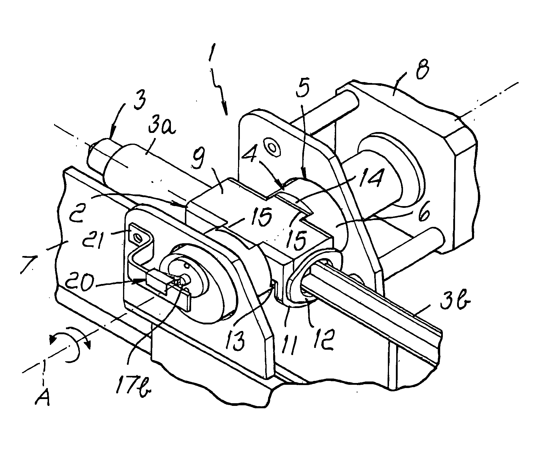
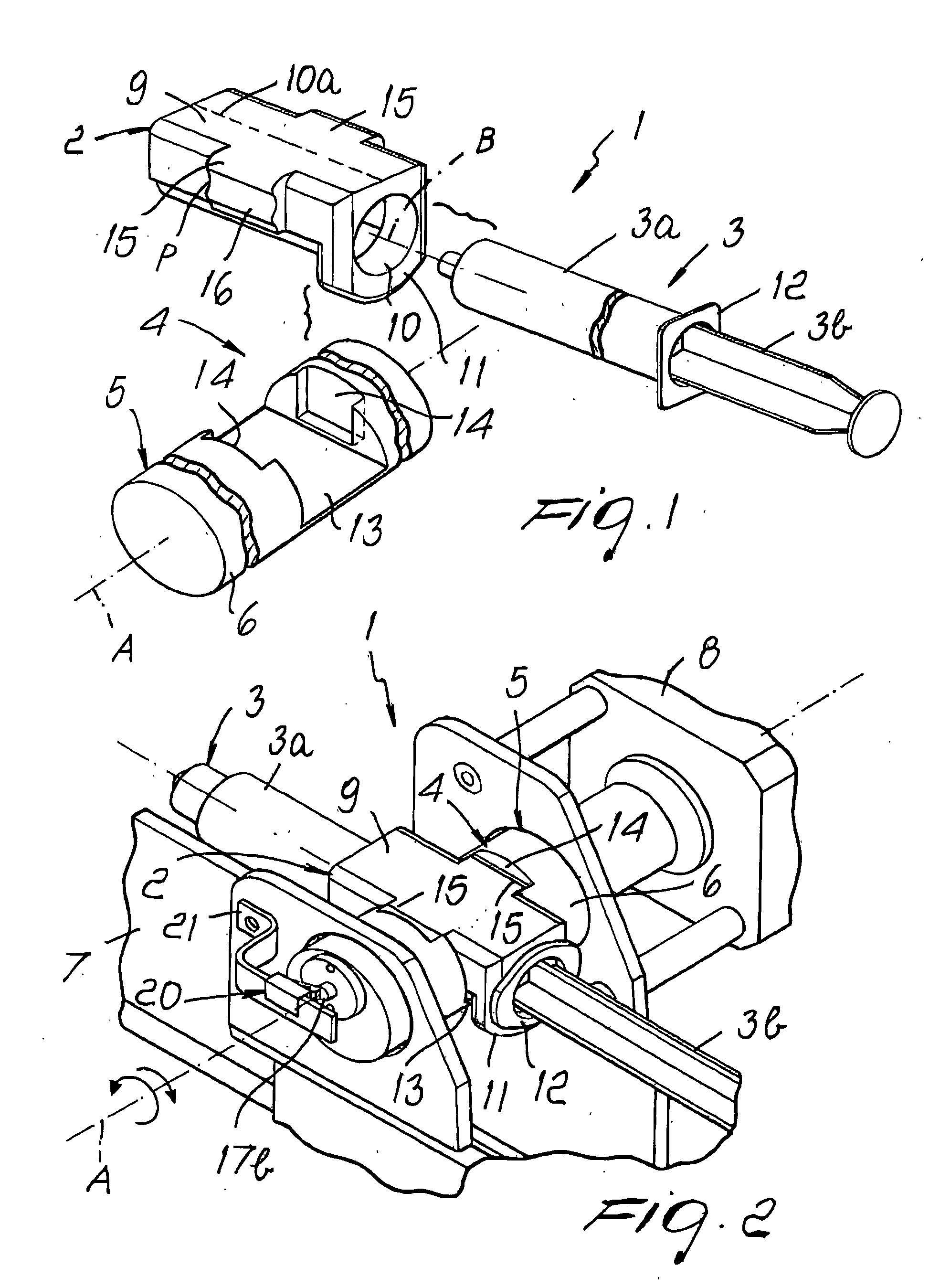
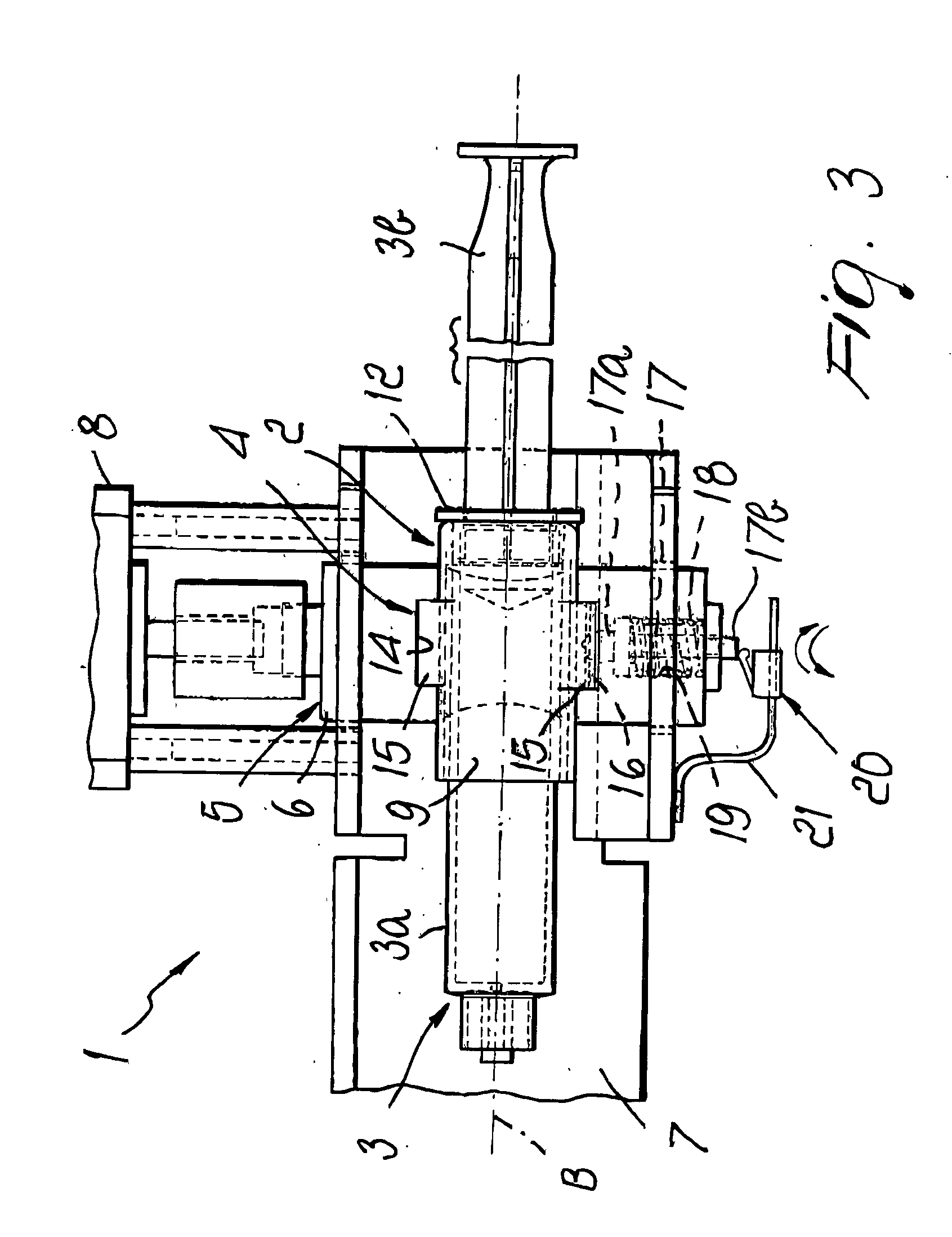
[0015] With reference to the figures, the reference numeral 1 generally designates a device for locking syringes to infusion pumps, which are generally not shown as they are of a known type.

[0016] The device 1 comprises supporting means 2 for supporting a syringe 3, of the type that comprises a substantially cylindrical body 3a and inside which a plunger 3b is inserted so that it can slide axially, said supporting means being rigidly associable with the body 3a, and coupling means 4 for temporarily coupling the supporting means 2 to an anchoring element 5 formed in a pump.

[0017] The anchoring element 5 can be constituted for example by a shaft 6, which is provided with a longitudinal axis A that is substantially perpendicular to a longitudinal axis B of the syringe 3, is arranged substantially horizontally, and is supported so that it can rotate about its own longitudinal axis A by a frame 7 of the pump.

[0018] The shaft 6 is associated with motor means 8, which are suitable to ro...


PUM


Abstract

A device for locking syringes to infusion pumps comprising elements for supporting a syringe, of the type that comprises a substantially cylindrical body inside which a plunger is inserted so that it can slide axially, the supporting element being rigidly associable with the substantially cylindrical body, and a coupling element for temporarily coupling the supporting element to an anchoring element of a pump.

Description

[0001] The present invention relates to a device for locking syringes to infusion pumps. BACKGROUND OF THE INVENTION [0002] Infusion pumps for syringes are known which are used in the therapeutic or diagnostic field for the controlled and automated infusion of drugs, contrast media or other fluids. [0003] Known pumps are substantially constituted by a supporting frame, with which means for locking the cylindrical body of a syringe and means of the linear automated type for actuating the sliding of the plunger of the syringe are associated. [0004] An electronic circuit controls and actuates the actuation means in order to dispense the fluid contained in the syringe according to an infusion program (time, flow-rate, speed et cetera) that can be set from the outside by an operator by means of a keypad and a display. [0005] Conventional locking means comprise a block, which is rigidly coupled to the pump frame and in which there is a slot in which it is possible to insert the wings form...

Claims


Application Information

Patent Timeline
IPC IPC(8): A61M5/142A61M5/145A61M39/10
CPCA61M2205/14A61M5/1456
Inventor AZZOLINI, GRAZIANO
Owner SIDAM DI AZZOLINI GRAZIANO E C
Why Eureka
Try Eureka