

Implantable acoustic sensor
- Summary
- Abstract
- Description
- Claims
- Application Information
AI Technical Summary
Problems solved by technology
Method used
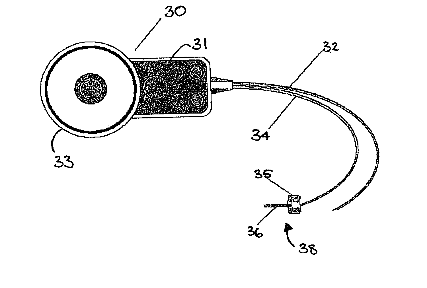
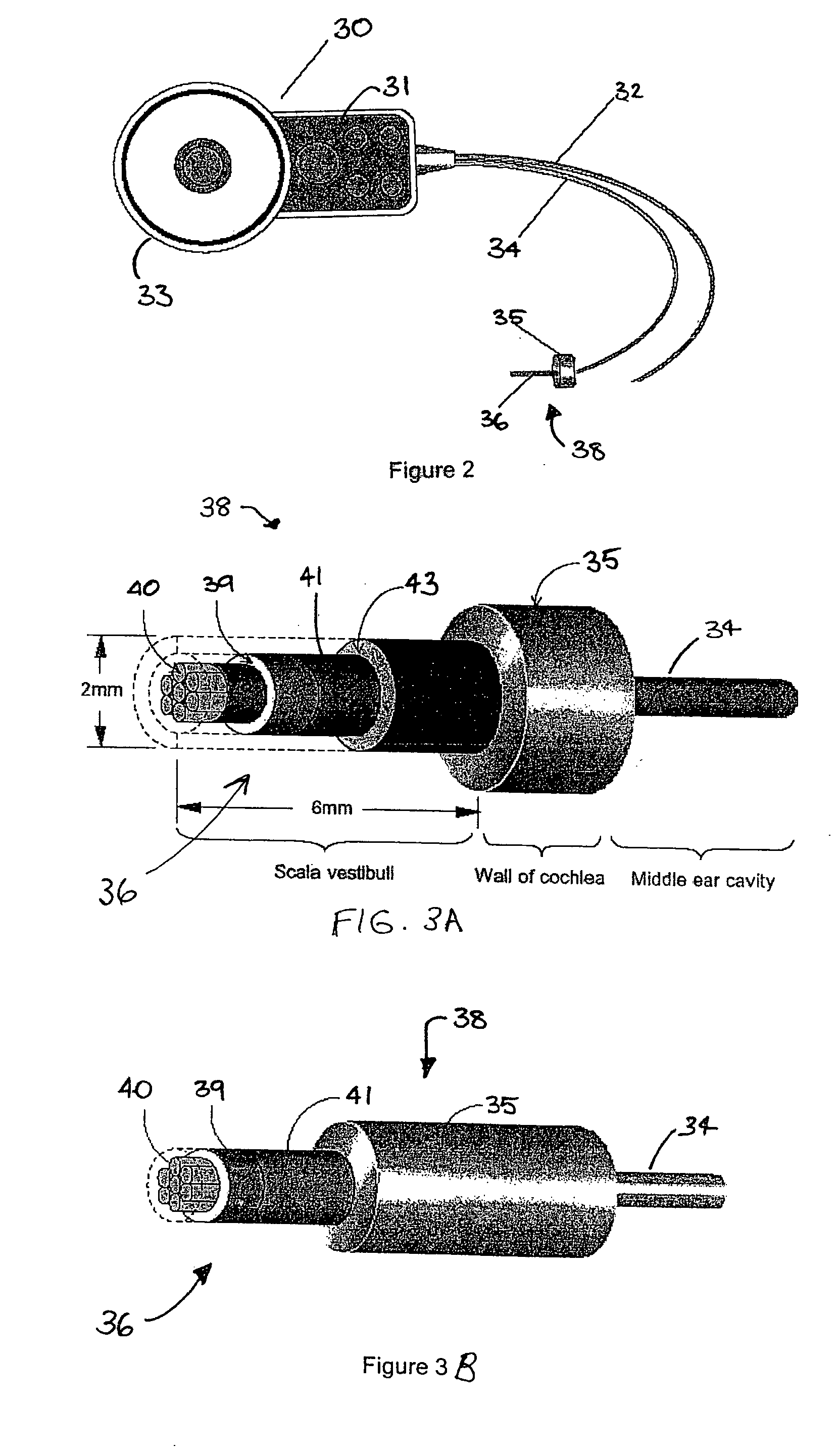
Image

Examples
Embodiment Construction
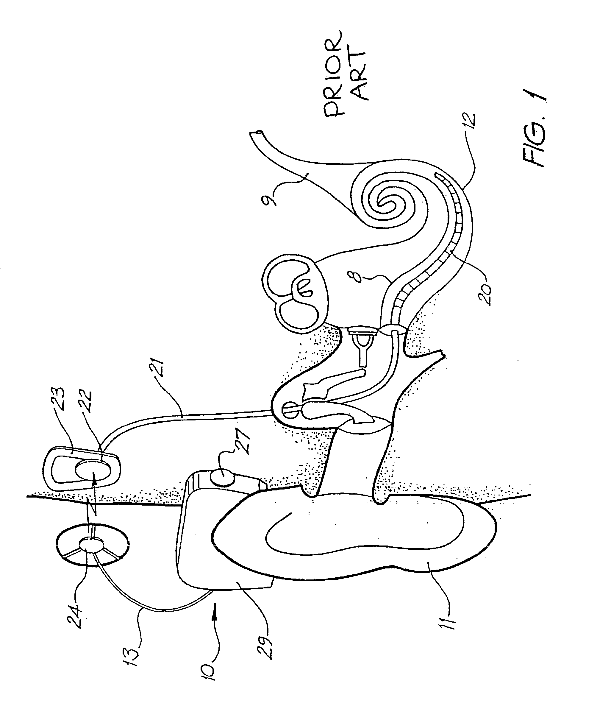
[0035] Before describing the features of the present invention, it is convenient to briefly describe the overall construction and function of a typical cochlear implant system.
[0036] Referring to FIG. 1, the cochlear implant system 10 includes two main parts, an external part including a speech processor 29, and an internal or implanted part including an implanted receiver and stimulator unit 22.
[0037] The external part includes a microphone 27. The speech processor 29 is, in this illustration, constructed and arranged so that it can fit behind the outer ear 11 and is held in place behind the outer ear 11 via an ear-hook arrangement (not shown). Alternative versions may be worn on the body. Attached to the speech processor 29 is a transmitter coil 24 that transmits electrical signals to the implanted unit 22 via a radio frequency (RF) link.
[0038] The implanted part includes a receiver coil 23 for receiving power and data from the transmitter coil 24. A cable 21 extends from the i...
PUM
 Abstract
Description
Claims
Application Information