
System and method for efficient analysis of transmission lines

a transmission line and efficient technology, applied in waveguides, waveguide type devices, instruments, etc., can solve the problems of increasing complexity as the number of lines increases, prior art is limited in the number of coupled lines or wired they can analyze simultaneously, and the noise coupled between transmission lines needs to be understood and minimized

Active Publication Date: 2005-08-11
TWITTER INC
View PDF5 Cites 2 Cited by
  • Summary
  • Abstract
  • Description
  • Claims
  • Application Information

AI Technical Summary

Benefits of technology

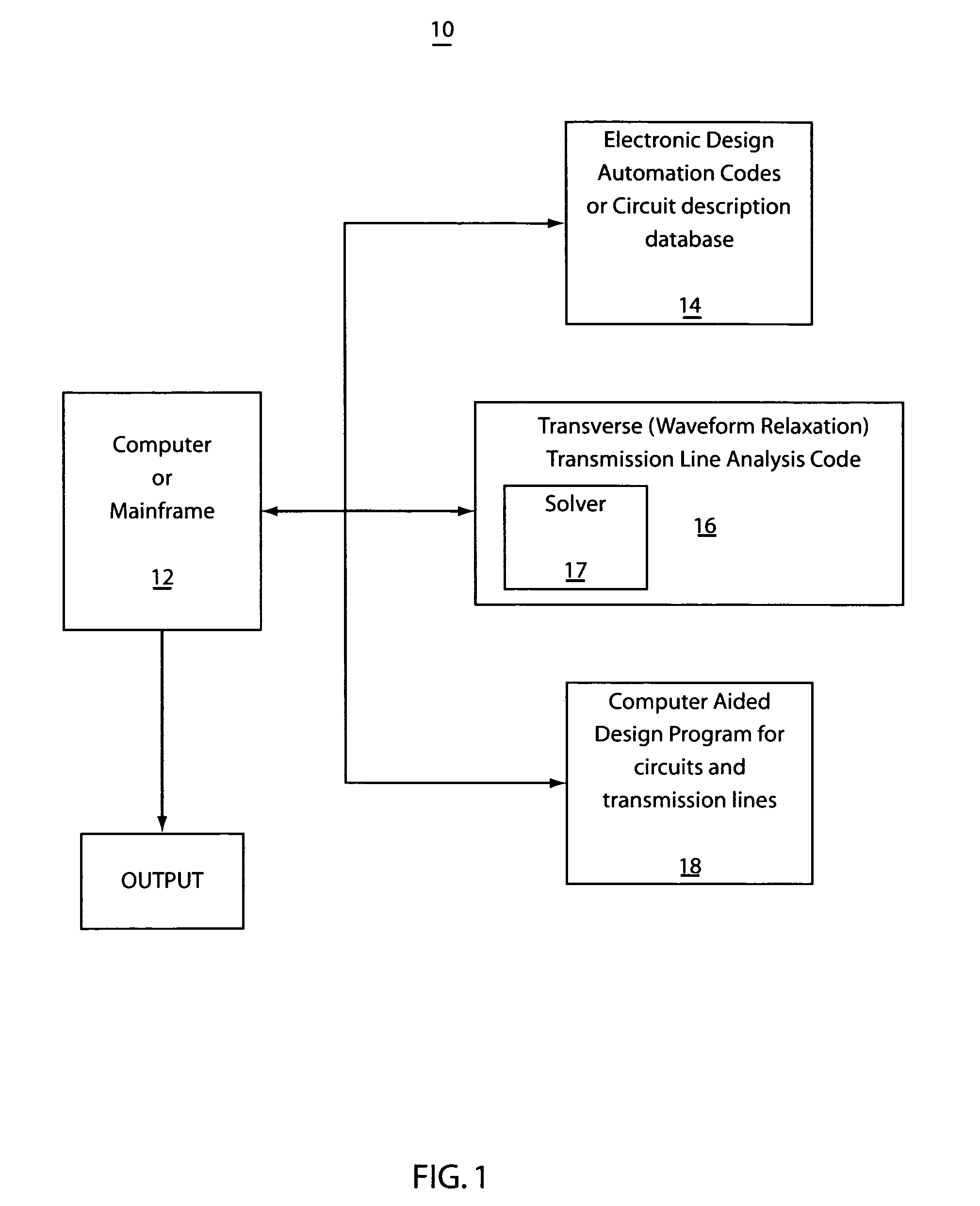
[0012] A computer system for analyzing one or more electrical circuits, the electrical circuits having two or more coupled lines, one of the lines being a victim line and one or more of the lines being an aggressor line includes one or more circuit models and a transmission analysis process that selects one or more of the aggressor lines, being selected aggressor lines, and one or more rejected aggressor lines. The selected aggressor lines have a coupling factor with the victim line that is above a coupling threshold. A solver process is includes that performs a nonlinear circuit analysis on the circuit model using the victim line an

Problems solved by technology

Similar issues occur in electronic circuitry where noise coupled between transmission lines needs to be understood and minimized.
Such issues occur in, e.g. instrumentation and / or computer circuitry in racks or cabinets.
These techniques are suitable for the analysis of models with a few lines; however, the complexity increases rapidly as the number of lines increases.
The prior art is limited in the number of coupled lines or wired they can analyze simultaneously.
The complexity of the coupling calculation is increases rapidly as the number of lines increases, and the accuracy of the results decreases with the increasing number of lines.
Hence, the prior art is unable to handle a large number of lines due to excessive computation time and the results become questionable.
These approaches are therefore unsuitable for handling even typical transmission line circuits, which include surrounding nonlinear drivers and receivers.

Method used


Image

  • System and method for efficient analysis of transmission lines
  • System and method for efficient analysis of transmission lines
  • System and method for efficient analysis of transmission lines

Examples


Embodiment Construction

[0022] The present invention provides systems and methods for analyzing electrical circuits with transmission lines. In particular, the present invention provides ways for accounting for noise and other coupled effects from multiple neighboring lines and from the surroundings.

[0023] One embodiment of the present invention in includes a system and method for analyzing one or more electrical circuits where the electrical circuits have two or more coupled lines. One or more of the lines may be referred to as victim lines and one or more of the other lines may be referred to as an aggressor line or lines. The system provides one or more circuit models and a transmission analysis process that selects one or more of the aggressor lines (selected aggressor lines) and one or more rejected aggressor lines. The selected aggressor lines include a coupling factor with victim lines that have a value above a coupling threshold. A solver process performs a non-linear circuit analysis on the circu...


PUM


Abstract

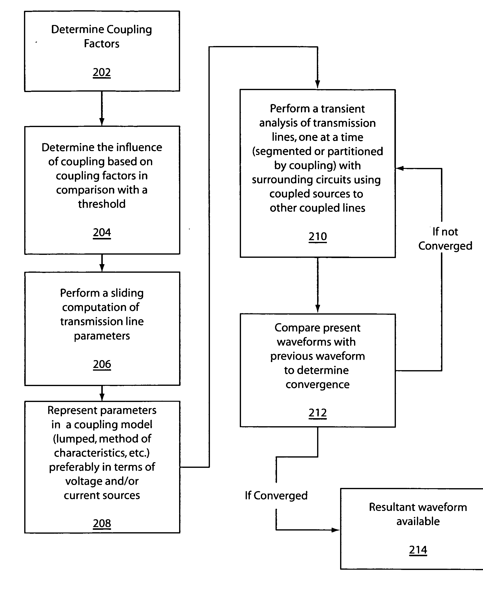
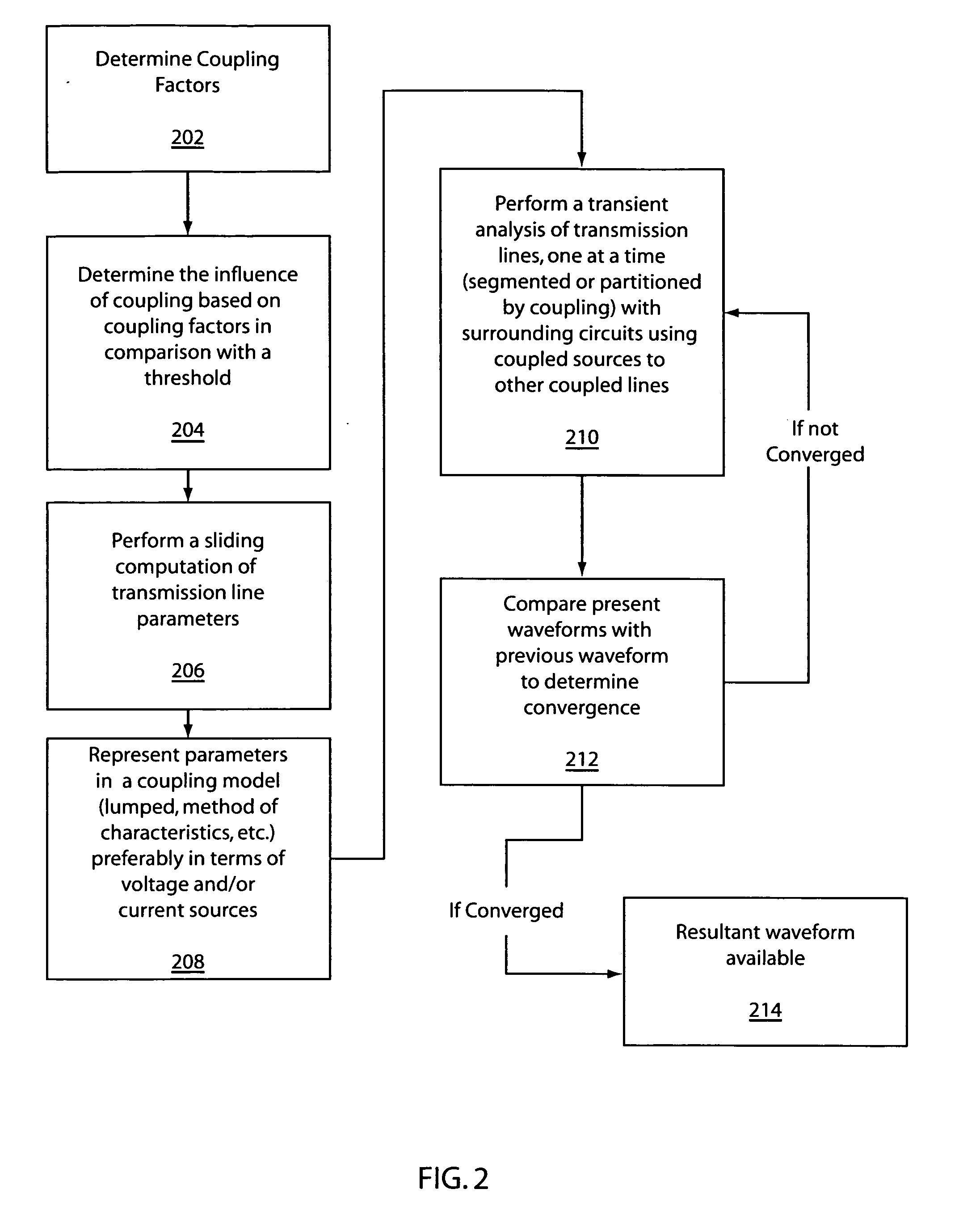
A system and method for analyzing a circuit with transmission lines includes determining which sources influence each of a plurality of transmission lines, based on coupling factors. Transmission line parameters are computed based on the sources, which influence each transmission line. A transient response or frequency response is analyzed for each transmission line by segmenting each line to perform an analysis on that line. The step of analyzing is repeated using waveforms determined in a previous iteration until convergence to a resultant waveform has occurred.

Description

BACKGROUND OF THE INVENTION [0001] 1. Field of the Invention [0002] The present invention relates to electrical circuit analysis, and more particularly to analysis of circuits, which involve transmission lines. [0003] 2. Description of the Related Art [0004] Electrical circuits with transmission lines are analyzed using circuits and numerical techniques to ensure proper functioning of the circuits. Examples of such circuits include power distribution systems, which need to be analyzed for stability and other properties. The coupling and coupled signals between multiple lines is an important aspect of these power distribution systems. [0005] Another example includes the analysis of circuits on microprocessor chips where a bus with hundreds of wires is to be analyzed to determine whether the wire to wire coupling is excessive. [0006] Similar issues occur in electronic circuitry where noise coupled between transmission lines needs to be understood and minimized. Such issues occur in, e...

Claims


Application Information

Patent Timeline
IPC IPC(8): G01R15/00G01R31/28
CPCG01R31/2813
Inventor DEUTSCH, ALINAFELDMANN, PETERRUEHLI, ALBERT E.SMITH, HOWARD HAROLD
Owner TWITTER INC
Learn More