
Collapsible laundry rack

Inactive Publication Date: 2005-08-18
LA LA IMPORTS LP
View PDF11 Cites 7 Cited by
  • Summary
  • Abstract
  • Description
  • Claims
  • Application Information

AI Technical Summary

Benefits of technology

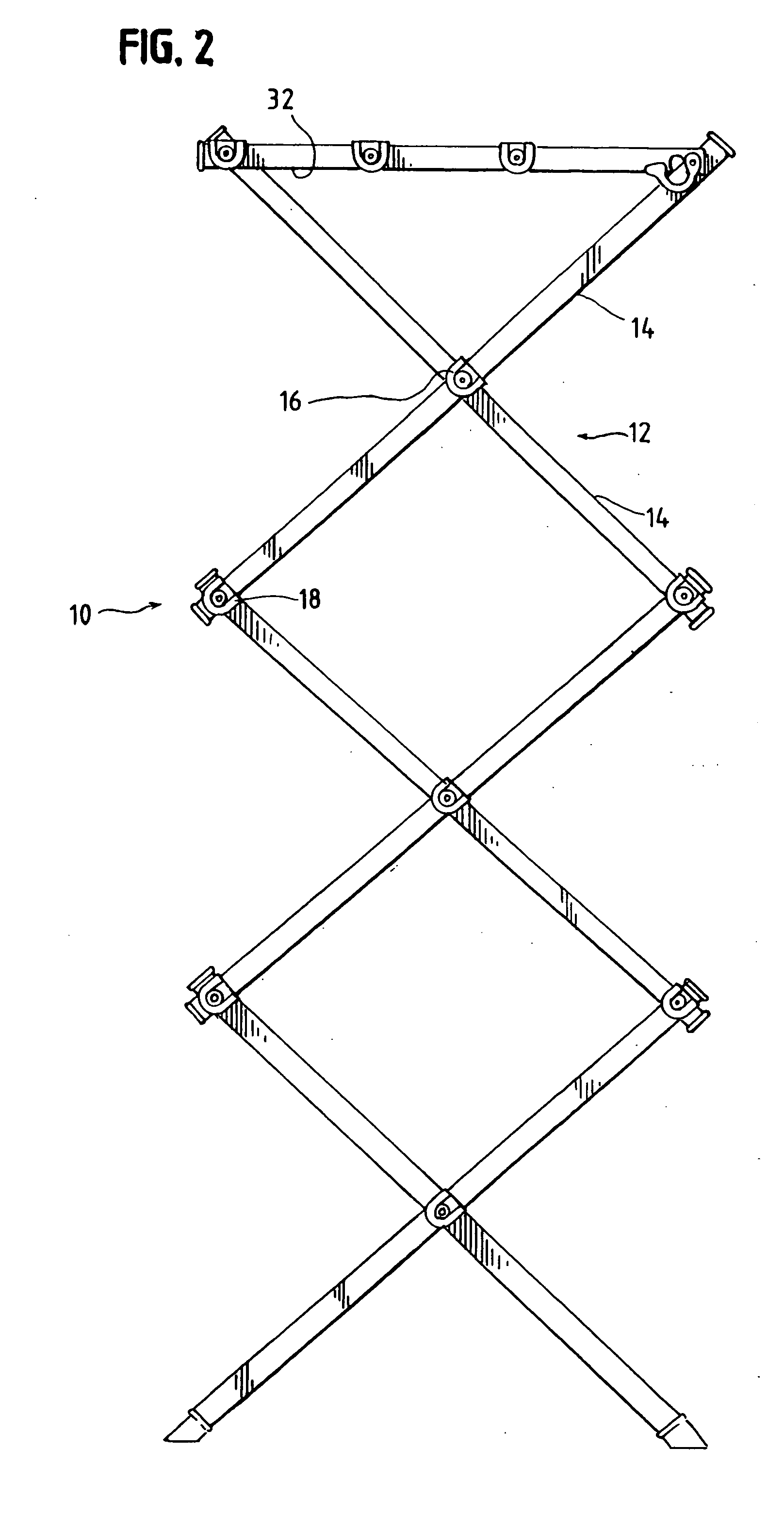
[0019] The rack may include at least one scissor-type linkage forming at least part of each of the legs. Each of the linkages may have a pair of members being pivotally connected between their ends to convert the laundry rack between an expanded position and a collapsed position. The linkages may be in a

Problems solved by technology

While advantageously eliminating assembly operations by the consumer, such racks, even in their collapsed configurations, can be bulky.
When shipping racks from overseas, shipping costs can be higher for bulky, space consuming racks in their collapsed states as compared to the disassembled components of the racks.
The bulkiness of collapsed racks having the legs permanently connected to the cross supports can also disadvantageously require an increased amount of shelf space in stores as compared to the various components of the rack disassembled.
However, assembly of these racks can be difficult, requiring complex manipulations of the components and sometimes tools to permit assembly by the consumer or end user.
Due to the number of cross supports, typically three or more, insertion of the cross supports into the holes in the second of the pair of legs can be difficult, requiring that each of the holes simultaneously be aligned with the ends of the cross supports before any of the cross supports are inserted into the holes.
However, the friction fits between each of the holes and cross supports can vary, potentially causing difficulties in ass

Method used


Image

  • Collapsible laundry rack
  • Collapsible laundry rack
  • Collapsible laundry rack

Examples


Example

DETAILED DESCRIPTION OF THE DRAWINGS

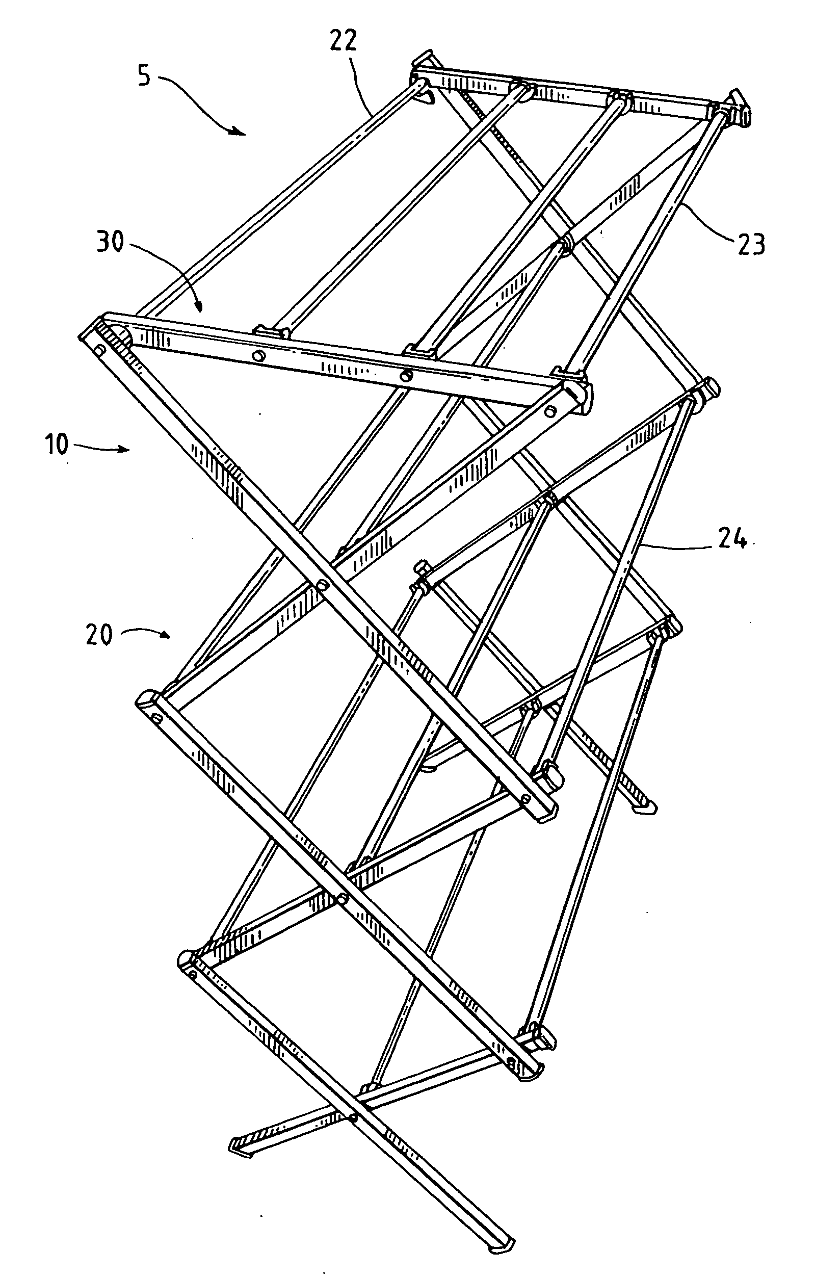
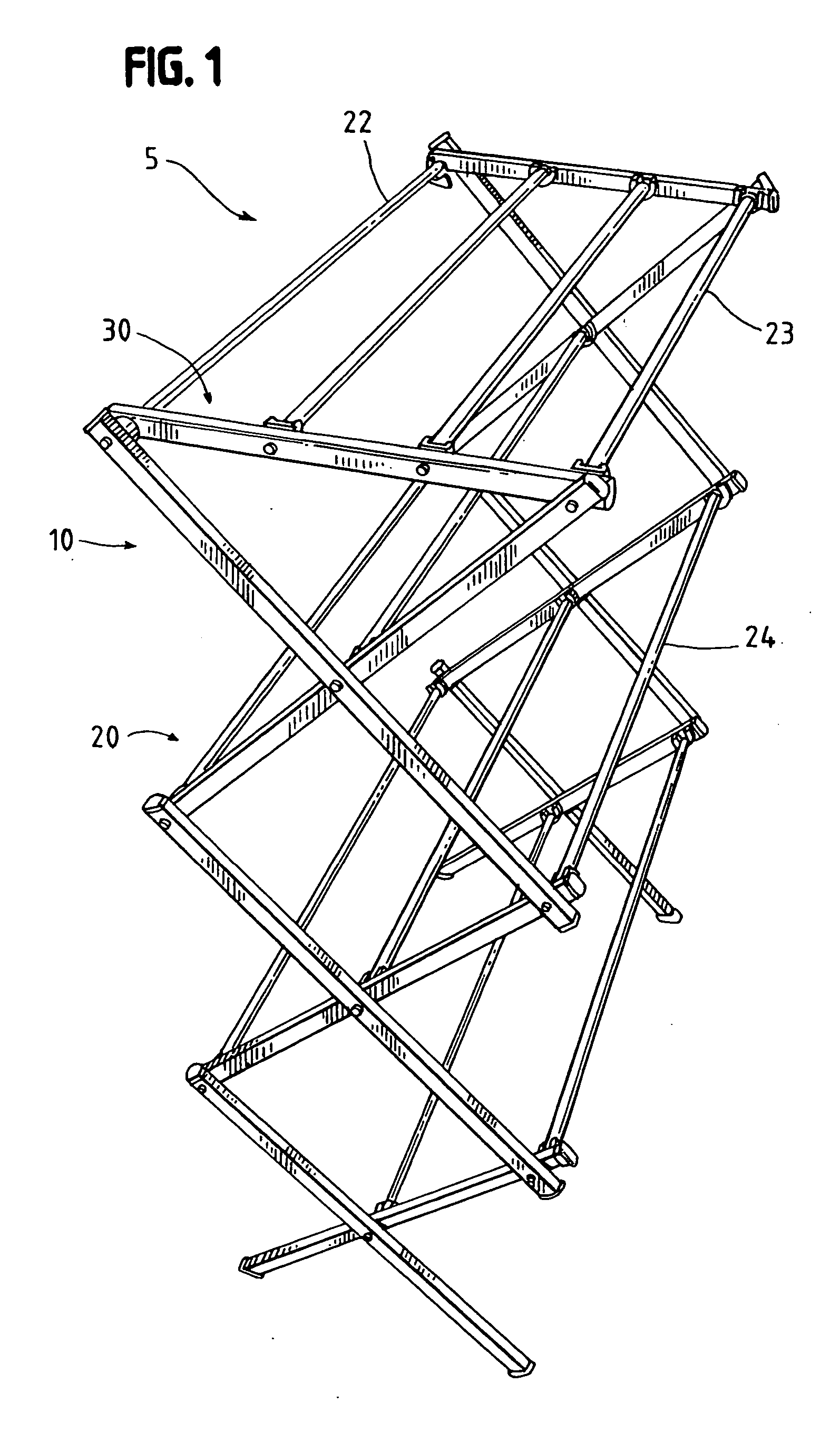
[0040] The laundry rack 5 is preferably embodied in a collapsible rack 5 having a pair of legs 10 connected by cross members 20. The connections between the cross members 20 and legs 10 are configured for simplified assembly and disassembly. Preferred embodiments of the laundry rack 5 are disclosed below. FIGS. 1-13 illustrate a laundry rack 5 having connectors between cross members 20 and legs 10 that promote simplified assembly and disassembly of the components. These components include a pair of legs 10 connected by cross members 20, as shown in FIG. 1. In the illustrated embodiment, the legs 10 are vertically extending and the cross members 20 are horizontally extending between the legs 10.

[0041] The drying rack 5 is shiftable between a collapsed position, as shown in FIG. 3, and an expanded or upright position as shown in FIG. 1. The collapsed position allows for simplified storage of the drying rack 5, as it can take up less space than the...


PUM


Abstract

A collapsible laundry rack is provided that can be formed from a pair of collapsible legs and a plurality of cross members extending between the legs. A connector is provided between the cross members and the legs to secure the cross members relative to the legs. The connector is configured to allow for sequential assembly and disassembly of the cross members relative to the legs in order to simply assembly and disassembly operations.

Description

CROSS-REFERENCE TO RELATED APPLICATION [0001] This application is a continuation-in-part of application Ser. No. 10 / 664,580, filed on Sep. 16, 2003.FIELD OF THE INVENTION [0002] The invention relates generally to connectors for connecting components of laundry and storage devices, and particularly to connectors for connecting components of a collapsible laundry rack. BACKGROUND OF THE INVENTION [0003] Laundry racks or drying racks typically consist of a pair of legs connected by cross supports. The legs are formed of a plurality of members in a scissor-type linkage arrangement, allowing the legs, and thus the racks, to be converted from a collapsed position to an expanded position. In the collapsed position, the racks can be smaller in size than the expanded position and more readily stored. In the expanded position, the racks can be used to hang various articles, such as clothes, over the legs and cross supports. [0004] In one form of racks or stands, the cross supports are permane...

Claims


Application Information

Patent Timeline
IPC IPC(8): A47F7/00A47F7/16D06F57/08D06F57/10
CPCD06F57/10D06F57/08
Inventor LI, XIANGMING
Owner LA LA IMPORTS LP
Learn More