
Quick-adjusting mounting head

a mounting head and quick technology, applied in the field of mounting hardware, can solve the problems of cumbersome use and difficult holding steady by hand of the scope, and achieve the effect of convenient adjustment of the scop

Active Publication Date: 2005-08-18
BRANDES RAYMOND V
View PDF25 Cites 13 Cited by
  • Summary
  • Abstract
  • Description
  • Claims
  • Application Information

AI Technical Summary

Benefits of technology

[0009] The present invention comprises an easily adjustable scope mounting head and stand. The stand includes a stabilized base with a vertical rod extending upward. The scope mounting head is attached to the vertical rod. A ball and socket joint is located on one end of the mounting head and an adjusting knob is located on the opposite end. The ball is equipped with accessible mounting means for attaching a spotting scope or similar article. When the user slackens the adjusting knob, the ball and socket joint is free to move in roll, pitch, and yaw. In addition, the entire mounting head can rotate about the vertical rod and slide up and down the vertical rod. When the user tightens the adjusting knob, all degrees of freedom are locked. Thus, the single adjusting knob provides all needed adjustment for the height and orientation of the spotting scope.

Problems solved by technology

Such scopes are difficult to hold steadily by hand.
These are cumbersome to use.

Method used


Image

  • Quick-adjusting mounting head
  • Quick-adjusting mounting head
  • Quick-adjusting mounting head

Examples


Embodiment Construction

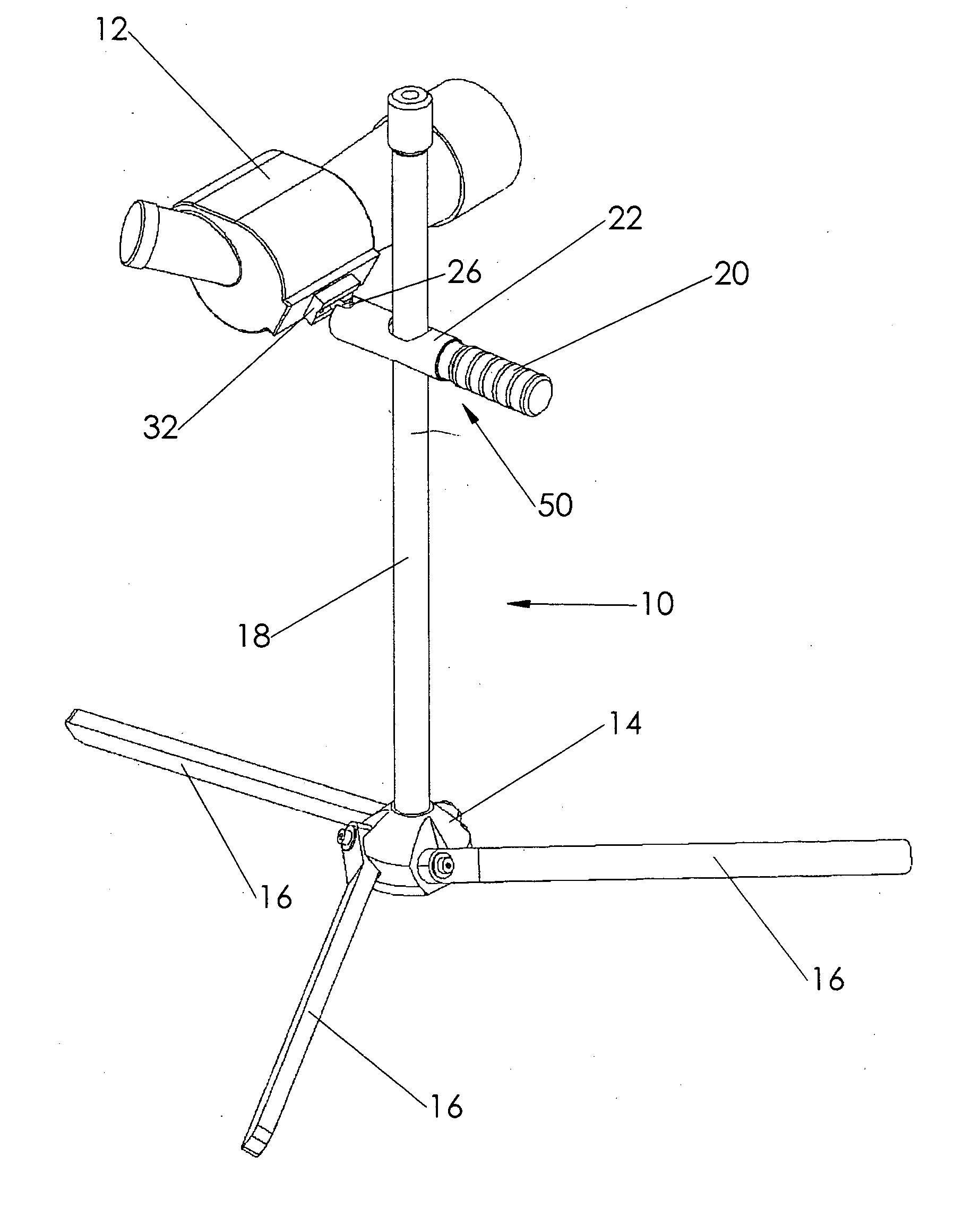
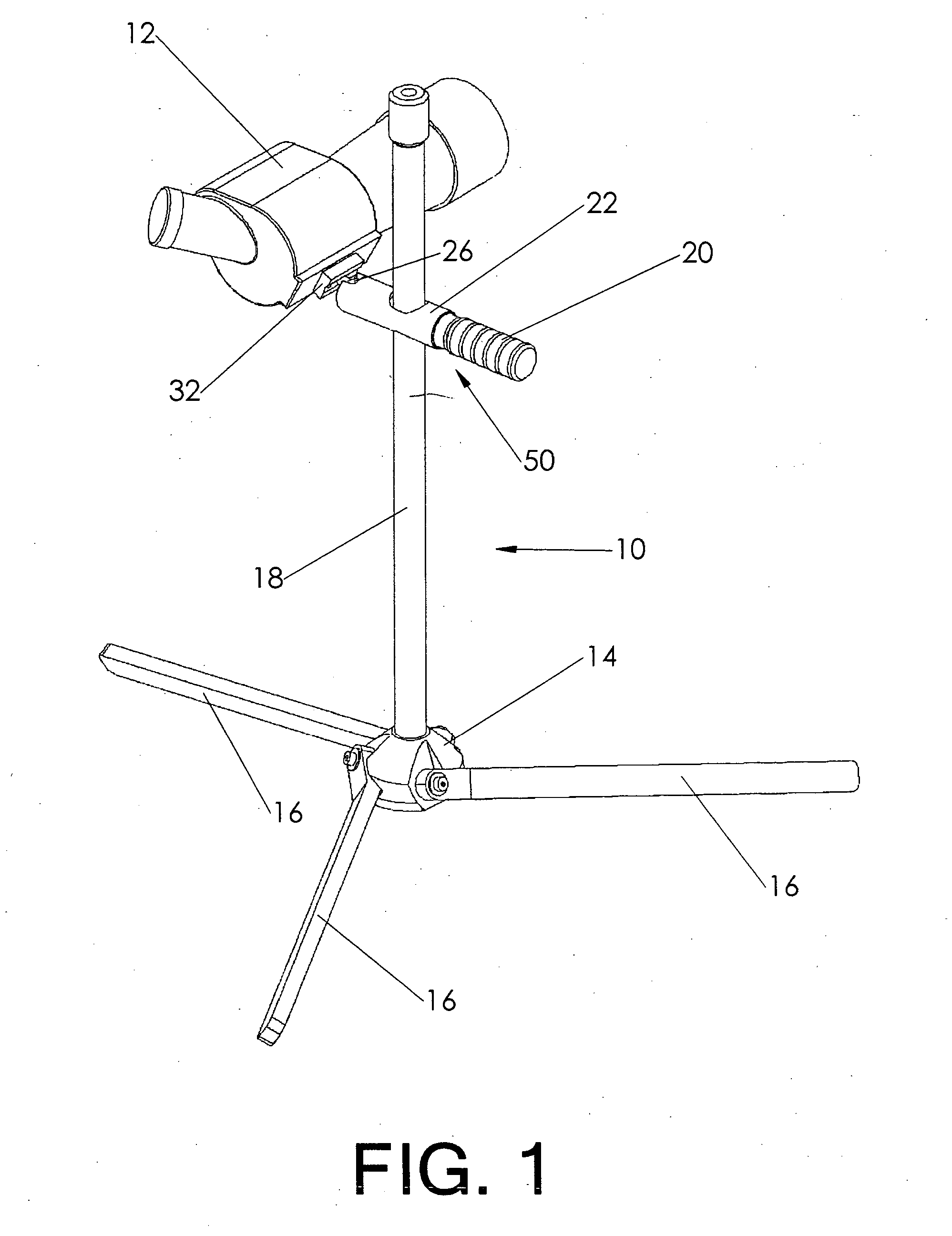
[0056]FIG. 1 shows the present invention set up for use. Stand 10 includes rod 18 supported by a tripod configuration of three legs 16 attached to base 14. Mounting head 50 attaches to rod 18 and secures spotting scope 12 in a desired position and orientation.

[0057] When adjusting knob 20 is loosened, ball 26 is free to move within a ball and socket joint (free to move in roll, pitch, and yaw). This allows mounting plate 32, with spotting scope 12 attached, to move in roll pitch, and yaw. Likewise, mounting head 50 is free to slide up and down rod 18, and to yaw around rod 18. When adjusting knob 20 is tightened, all the degrees of freedom just mentioned are locked. Thus, the reader will appreciate that the loosening or tightening of the single adjusting knob allows complete adjustment of the position and orientation of spotting scope 12.

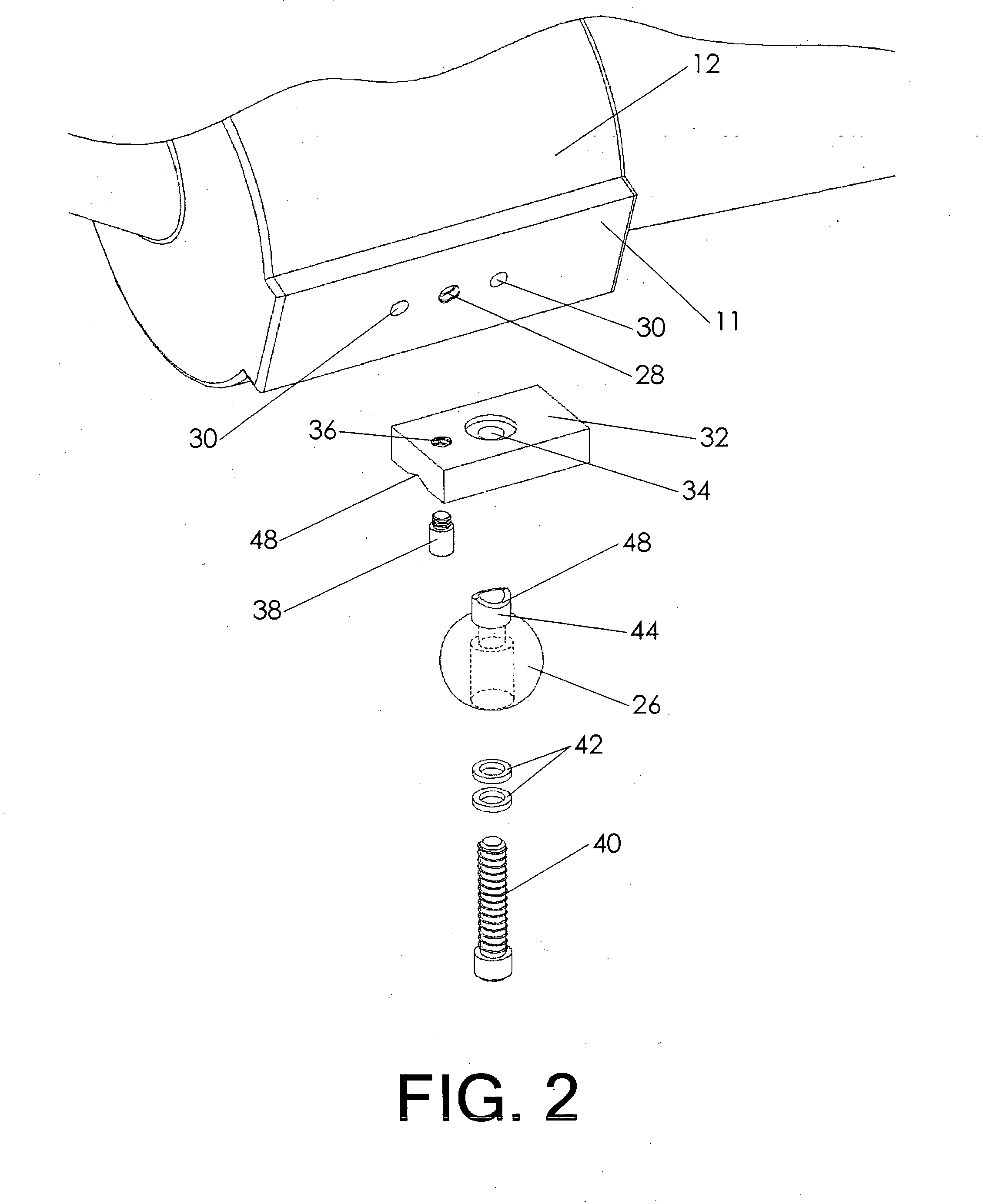
[0058]FIG. 2 is an exploded view showing how ball 26 is attached to the spotting scope. The spotting scope features scope attachment plate 11, wh...


PUM


Abstract

An easily adjustable scope mounting head and stand. The stand includes a stabilized base with a vertical rod extending upward. The scope mounting head is attached to the vertical rod. A ball and socket joint is located on one end of the mounting head and an adjusting knob is located on the opposite end. The ball is equipped with accessible mounting mens for attaching a spotting scope or similar article. When the user slackens the adjusting knob, the ball and socket joint is free to move in roll, pitch, and yaw. In addition, the entire mounting head can rotate about the vertical rod and slide up and down the vertical rod. When the user tightens the adjusting knob, all degrees of freedom are locked. Thus, the single adjusting knob provides all needed adjustment for the height and orientation of the spotting scope.

Description

BACKGROUND OF THE INVENTION [0001] 1. Field of the Invention [0002] This invention relates to the field of mounting hardware. More specifically, the invention comprises a stand and adjustable mounting head which can be used to adjustably mount a piece of hardware such as a spotting scope. [0003] 2. Description of the Related Art [0004] Telescopic “spotting scopes” have been in common use for many years. These optical devices are used to visually inspect objects at great distances. They require substantial magnification, typically in the range of 20× to 50×. Such scopes are difficult to hold steadily by hand. They are therefore often mounted on a tripod. [0005] One common use for such spotting scopes is in the field of target shooting. Targets may be located 300 yards or more away from the shooter. The spotting scope must be aimed at the target, and must provide enough magnification for the shooter to accurately see the bullet strikes on the target (often holes in a piece of paper). ...

Claims


Application Information

Patent Timeline
Patent Type & Authority Applications(United States)
IPC IPC(8): F16M11/14F16M11/16F16M11/20F16M11/24
CPCF16M11/14F16M11/16F16M2200/027F16M11/2014F16M11/24F16M11/20
Inventor BRANDES, RAYMOND V.
Owner BRANDES RAYMOND V
Learn More