Antenna unit

a technology of antenna unit and antenna unit, applied in the field of antenna unit, can solve the problems of restricting the conformity of the outer shape of the structure attached to the outside of the vehicle, and achieve the effect of alleviating the gain of the second elemen

Inactive Publication Date: 2005-08-18
CLARION CO LTD
View PDF4 Cites 3 Cited by
  • Summary
  • Abstract
  • Description
  • Claims
  • Application Information

AI Technical Summary

Benefits of technology

[0014] According to the antenna unit of the invention, by forming a length of at least a portion of the transmitting path of the feeding conductor and the length of the second element by the lengths different from each other, the feeding conductor is made to be difficult to function as an element having a function

Problems solved by technology

However, an outer shape of a structure attached to outside of a vehicle is restricted in conformity with regulations.
Particularly, the restriction is severe in a direction of being projected from the vehicle

Method used


Image

  • Antenna unit
  • Antenna unit
  • Antenna unit

Examples


first embodiment

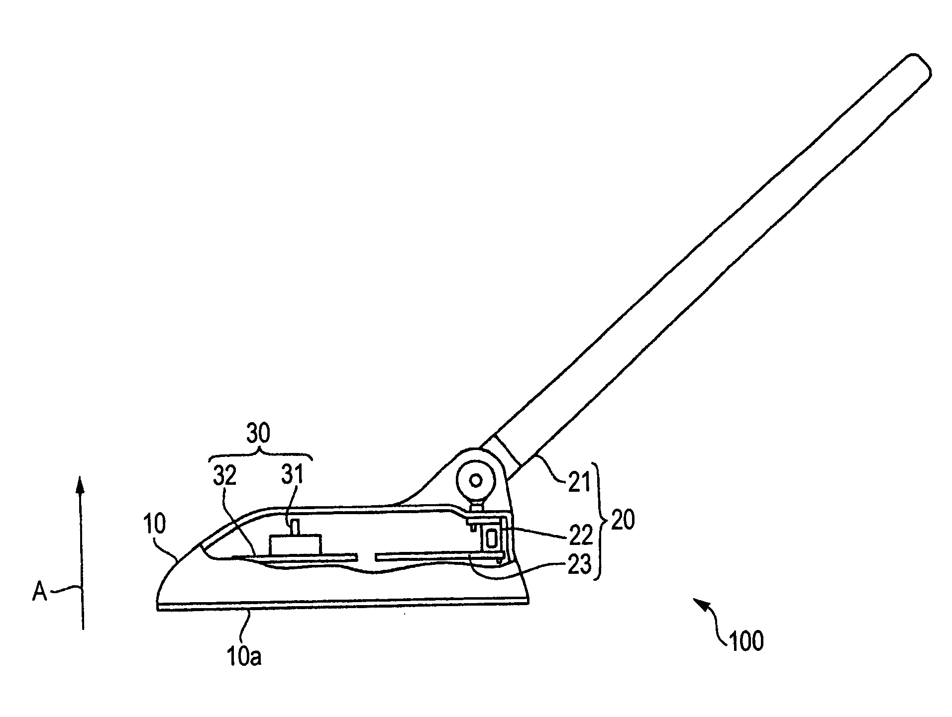
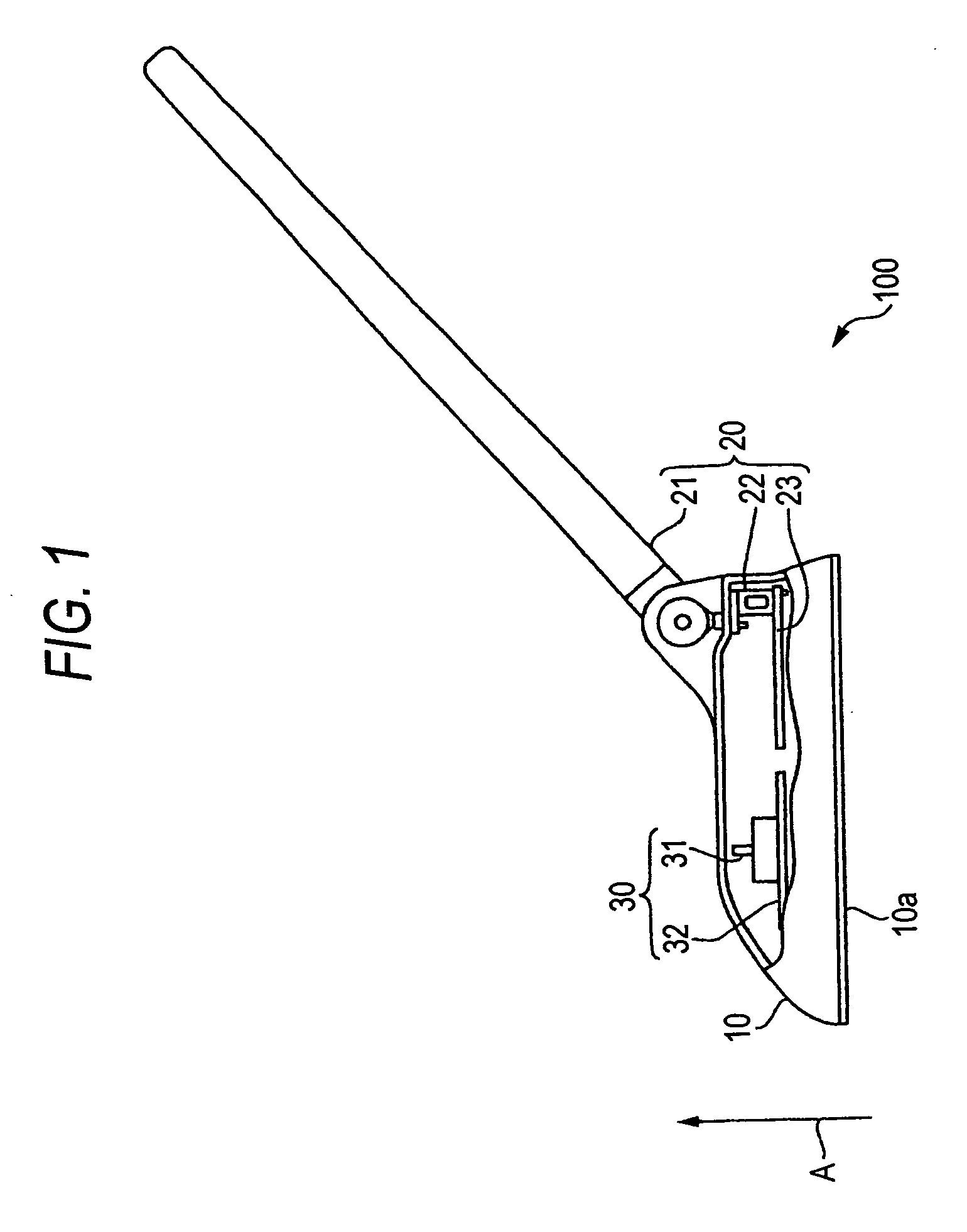
[0019] An antenna unit 100 according to the invention is a unit provided at a vehicle-mounted apparatus mounted to a vehicle and is a compound antenna provided with both a function of receiving AM / FM radio broadcast and a function of receiving a satellite radio broadcast.

[0020] The antenna unit 100 is used by being attached to outside of a vehicle in order to excellently receive various radio waves. As described above, a structure attached to outside of a vehicle is requested to be small-sized and therefore, the antenna unit 100 is devised to excellently receive various radio waves in a state of downsizing a shape thereof.

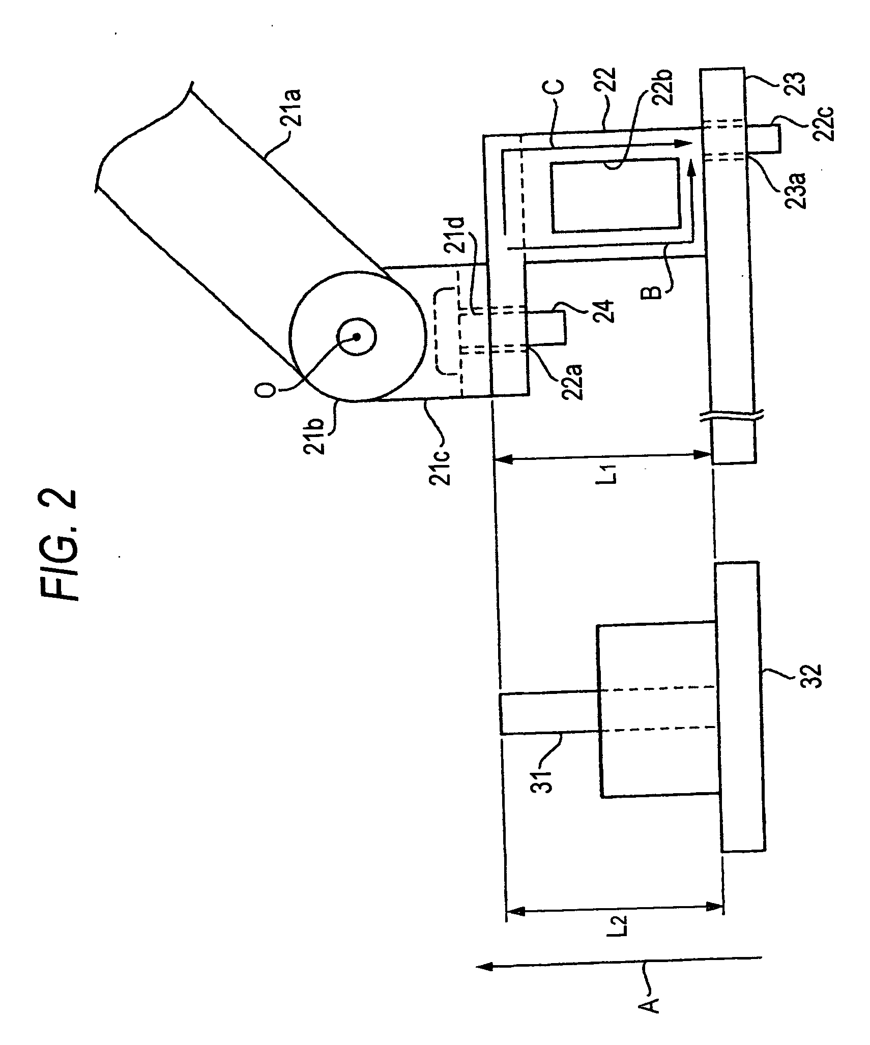
[0021]FIG. 1 is a sectional view showing a sectional shape of the antenna unit 100 according to the first embodiment of the invention. Further, FIG. 2 is a principal enlarged view showing to enlarge principal configurations at inside of the antenna unit 100 according to the first embodiment of the invention. An arrow mark A direction of FIG. 1 is a direction of pr...

second embodiment

[0036] According to the antenna unit of the second embodiment, the first antenna portion 20 includes the rod antenna 21, an attaching member 22z, the circuit board 23 and the attaching screw 24.

[0037] The attaching member 22z includes the hole portion 22a and the inserting portion 22c similar to those of the attaching member 22 of the first embodiment, and thereby, the rod antenna 21 and the circuit board 23 are brought into the state of being connected to each other electrically. Further, the attaching member 22z is provided with a detoured shape as shown in FIG. 3 with regard to a face thereof in parallel with paper face of FIG. 3. In other words, the attaching member 22z is formed as a member having a meandering structure with regard to the face in parallel with paper face of FIG. 3.

[0038] The attaching member 22z is provided with the length L1 which is a length substantially equivalent to the length L2 of the element 31 in the arrow mark A direction by reason similar to that of...


PUM


Abstract

An antenna unit including a first antenna portion including a first element, a first board for mounting the first element, and a feeding conductor for electrically connecting the first element and the first board and capable of receiving a radio wave in a first frequency band, and a second antenna portion including a second element shorter than the first element, and a second board for mounting the second element and capable of receiving a radio wave of a second frequency band higher than the first frequency band, in which a length of a transmitting path of the feeding conductor and a length of the second element are formed to configure lengths different from each other.

Description

BACKGROUND OF THE INVENTION [0001] 1. Field of the Invention [0002] The present invention relates to an antenna unit having a plurality of antenna portions capable of receiving radio waves of frequency bands different from each other. [0003] 2. Description of the Related Art [0004] In a conventional art, a rod antenna for receiving AM / FM radio waves is attached to a circuit board for functioning the antenna via an attaching member having conductivity. Up to the present date, in such a configuration, there has been proposed various antenna structures for achieving further excellent performance (for example, JP-A-2000-124722) . According to JP-A-2000-124722, an antenna unit is configured by inserting an attaching member to a circuit board in a state of being brought into contact with a rod antenna. [0005] In recent years, it is conceived to execute transmission and reception using various radio waves other than AM / FM radio waves in, for example, a vehicle-mounted apparatus and in acco...

Claims


Application Information

Patent Timeline
IPC IPC(8): H01Q1/22H01Q1/32H01Q1/52H01Q5/00H01Q21/28H01Q21/30
CPCH01Q1/3283H01Q21/30H01Q21/28
Inventor MATSUI, HIROYASUCHONAN, SUSUMUKUNII, TAKESHI
Owner CLARION CO LTD
Why Eureka
Try Eureka