
Gain adjustment method, gain adjustment circuit, and optical disc device having same gain adjustment circuit

a gain adjustment and gain adjustment technology, applied in the direction of recording signal processing, volume compression/expansion having semiconductor devices, instruments, etc., can solve the problems of detection circuit, inability to fix, and decrease in characteristics, so as to improve detection accuracy and reduce detection means sensitivity, the effect of reducing the detection means

Inactive Publication Date: 2008-05-20
SONY CORP
View PDF4 Cites 0 Cited by
  • Summary
  • Abstract
  • Description
  • Claims
  • Application Information

AI Technical Summary

Benefits of technology

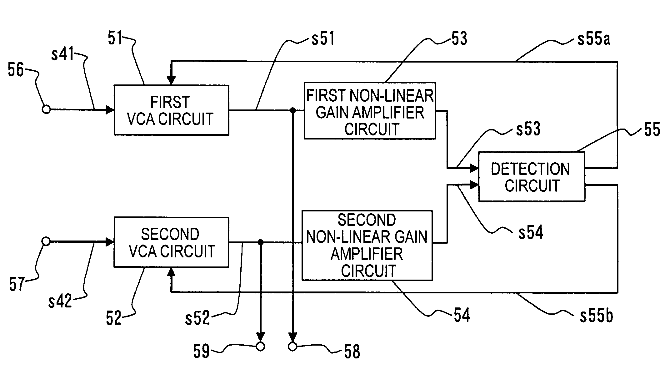
The present invention provides a gain adjustment circuit and an optical disc device including the circuit. The circuit can adjust the gains of different input signals while maintaining the relative levels of the signals. This prevents sensitivity variations in the detection circuit and improves the accuracy of the control signal, such as a wobble signal. The detection circuit detects a variable output signal of the gain varying means and the detection output signal is fed back to the gain varying means. This improves the detection accuracy and ensures a properly adjusted signal is output. The non-linear gain amplifying means can be easily configured and have a high response performance during a transient response. The optical disc device including the gain adjustment circuit improves the adjustment accuracy and operational stability.

Problems solved by technology

However, when it is desired to perform gain adjustment while maintaining the relative levels of different input signals as in the generation of the wobble signal, the input level of the output signal of each VCA circuit, which is input to the detection circuit, does not become fixed.
Moreover, there is a problem in that, because there is a case in which the sum of the output signals of each VCA circuit greatly varies, a decrease in characteristics occurs resulting from the sensitivity variations that occur in the detection circuit.
More specifically, there is the risk that because an offset of the detection circuit has a great effect on the amplitude of the output signal of each VCA circuit, which is input to the detection circuit, the balance at which the output signals of each VCA circuit are balanced varies.
As a result, there is the risk that the generation accuracy of the control signal, such as a wobble signal, decreases.

Method used


Image

  • Gain adjustment method, gain adjustment circuit, and optical disc device having same gain adjustment circuit
  • Gain adjustment method, gain adjustment circuit, and optical disc device having same gain adjustment circuit
  • Gain adjustment method, gain adjustment circuit, and optical disc device having same gain adjustment circuit

Examples


Embodiment Construction

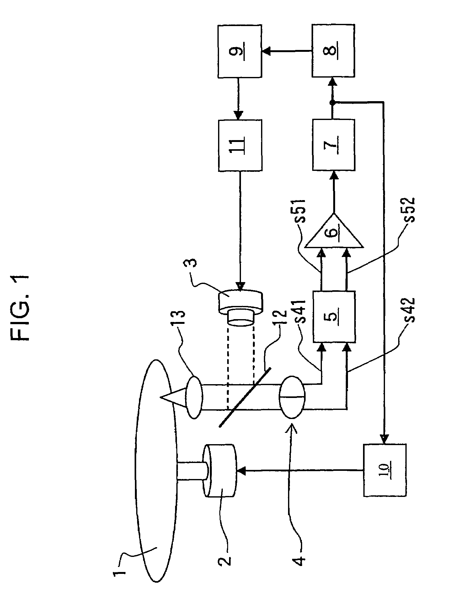
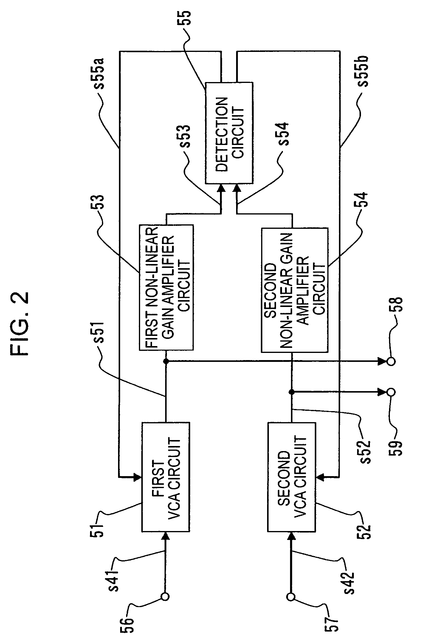
[0024]In a gain adjustment method, a gain adjustment circuit, and an optical disc device having the gain adjustment circuit according to an embodiment of the present invention, gain adjustment of a plurality of different signals is performed. Each of a plurality of different signals is input to gain varying means, the output signal of the gain varying means is input to one detection section, and the gain of each signal is adjusted while performing feedback control of the gain varying means.

[0025]In particular, before each signal output from the gain varying means is input to the detection section, each signal is input to a non-linear gain amplifier section, whereby gain adjustment is performed, and the signal that is gain-adjusted by the non-linear gain amplifier section is input to the detection section.

[0026]Here, the non-linear gain amplifier section is gain amplifying means for increasing the amount of change of the output gain in an area in which the level of the output signal ...


PUM


Abstract

A gain adjustment circuit includes a gain varying device for varying the gain of an input signal; and a detection device for detecting a variable output signal of the gain varying device, wherein the detection output signal of the detection device is fed back to the gain varying device.

Description

CROSS REFERENCES TO RELATED APPLICATIONS[0001]The present invention contains subject matter related to Japanese Patent Application JP 2004-309363 filed in the Japanese Patent Office on Oct. 25, 2004, the entire contents of which are incorporated herein by reference.BACKGROUND OF THE INVENTION[0002]1. Field of the Invention[0003]The present invention relates to a gain adjustment method, a gain adjustment circuit, and an optical disc device having the gain adjustment circuit. More particularly, the present invention relates to a gain adjustment method suitable for processing a wobble signal in a disk-shaped recording medium having wobbling grooves (guide grooves), a gain adjustment circuit for use therewith, and an optical disc device having the gain adjustment circuit.[0004]2. Description of the Related Art[0005]In the related art, in an optical disc device for recording predetermined data on a disk-shaped recording medium having wobbling grooves or for reproducing data recorded on a...

Claims


Application Information

Patent Timeline
Patent Type & Authority Patents(United States)
IPC IPC(8): H03F1/36
CPCG11B20/10009G11B20/10027H03G7/06H03G3/3084G11B2220/2537G11B2020/1238G11B20/10G11B7/004
Inventor DAIO, KATSUHISA
Owner SONY CORP
Learn More