

Mass spectrometer and mass spectrometry
a mass spectrometer and mass spectrometry technology, applied in mass spectrometers, particle separator tube details, separation processes, etc., can solve the problems of excessive high voltage, inability to start the discharge immediately, and difficulty in bringing a sample into fragmentation stably, so as to reduce the sensitivity, the effect of soft ionization
- Summary
- Abstract
- Description
- Claims
- Application Information
AI Technical Summary
Benefits of technology
Problems solved by technology
Method used
Image

Examples
first embodiment
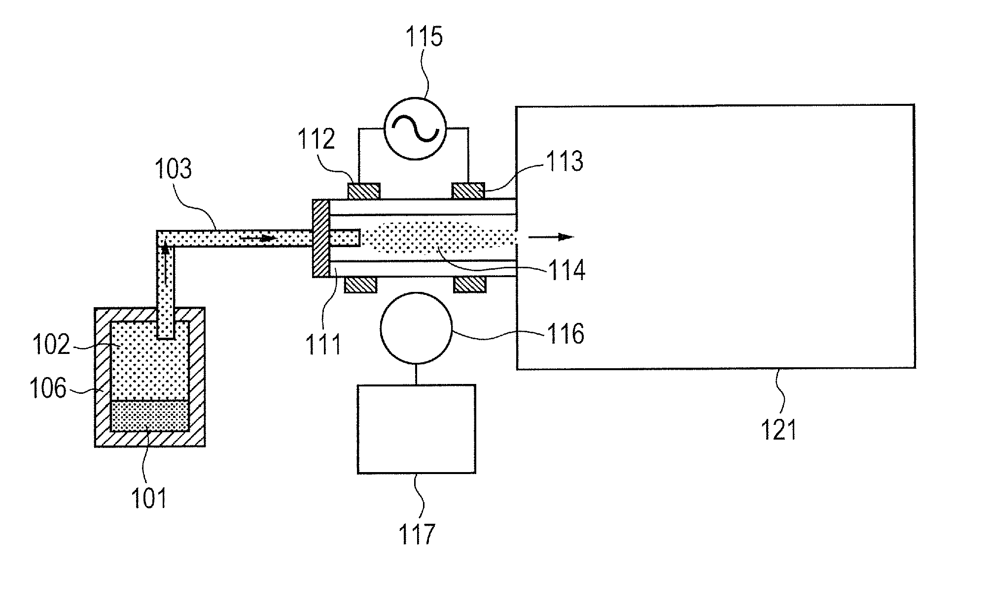
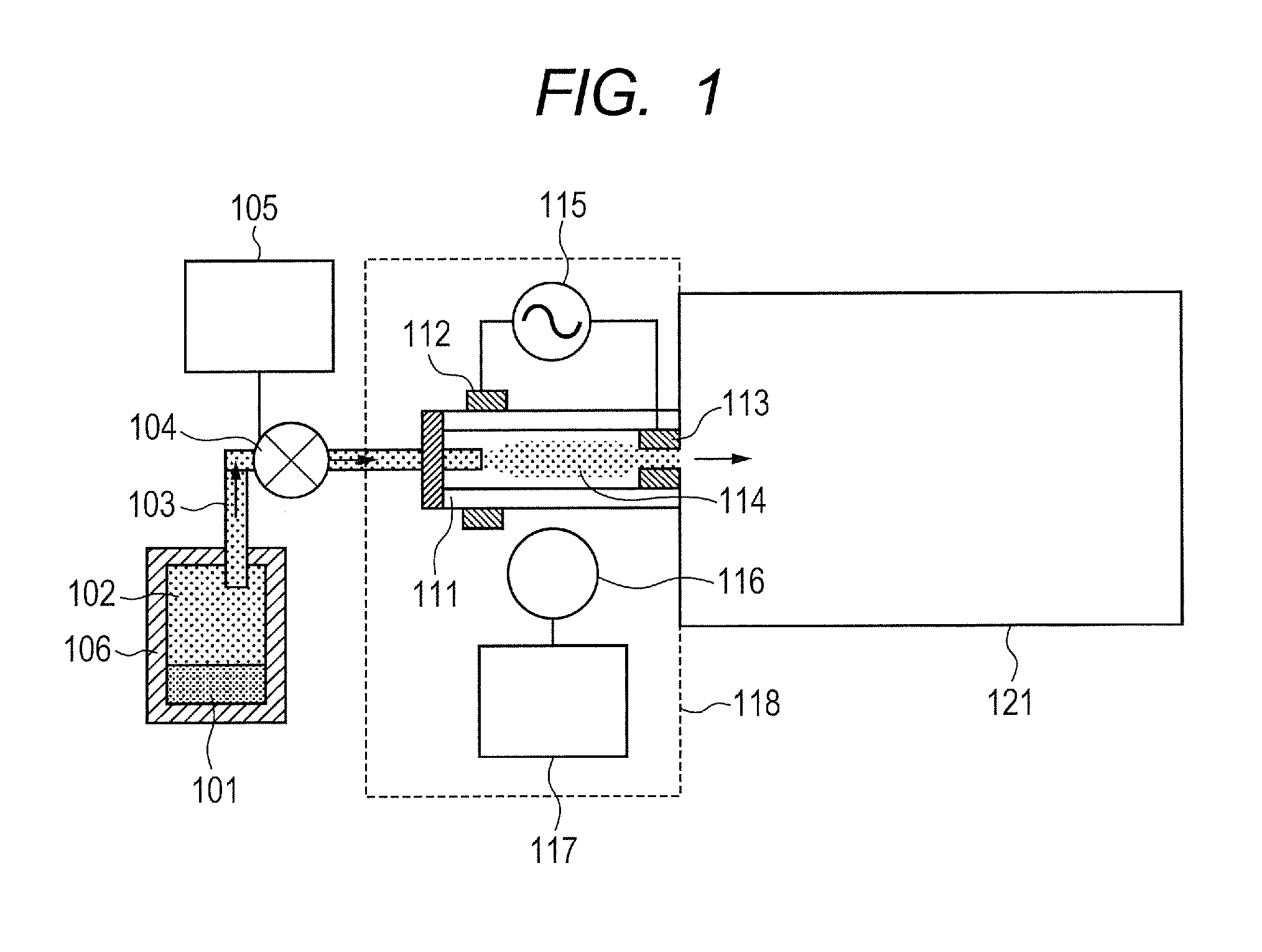
[0029]FIG. 1 shows an embodiment of the present invention. A sample 101 in a sample vessel 106 may be in any state of gas, liquid, or solid. In a case where the sample 101 is a liquid or a solid, the sample 101 put into the sample vessel 106 is evaporated at an ordinary temperature, or by heating. A gas 102 including the sample is introduced to an ion source unit as shown by a flow 103 of the sample by a pressure difference produced by a vacuum pump installed at amass spectrometry and ion detecting unit 121 only when a valve 104 is opened. The valve 104 is controlled to open and close by using a valve opening / closing control mechanism 105. According to the example, the valve is opened during a time period equal to or more than 5 ms and equal to or less than 200 ms.
[0030]The sample reaching a discharge area 114 is ionized by a dielectric barrier discharge generated by using a light transmitting dielectric 111 such as Pyrex glass, an electrode 112 for discharge on a side of a sample i...
second embodiment
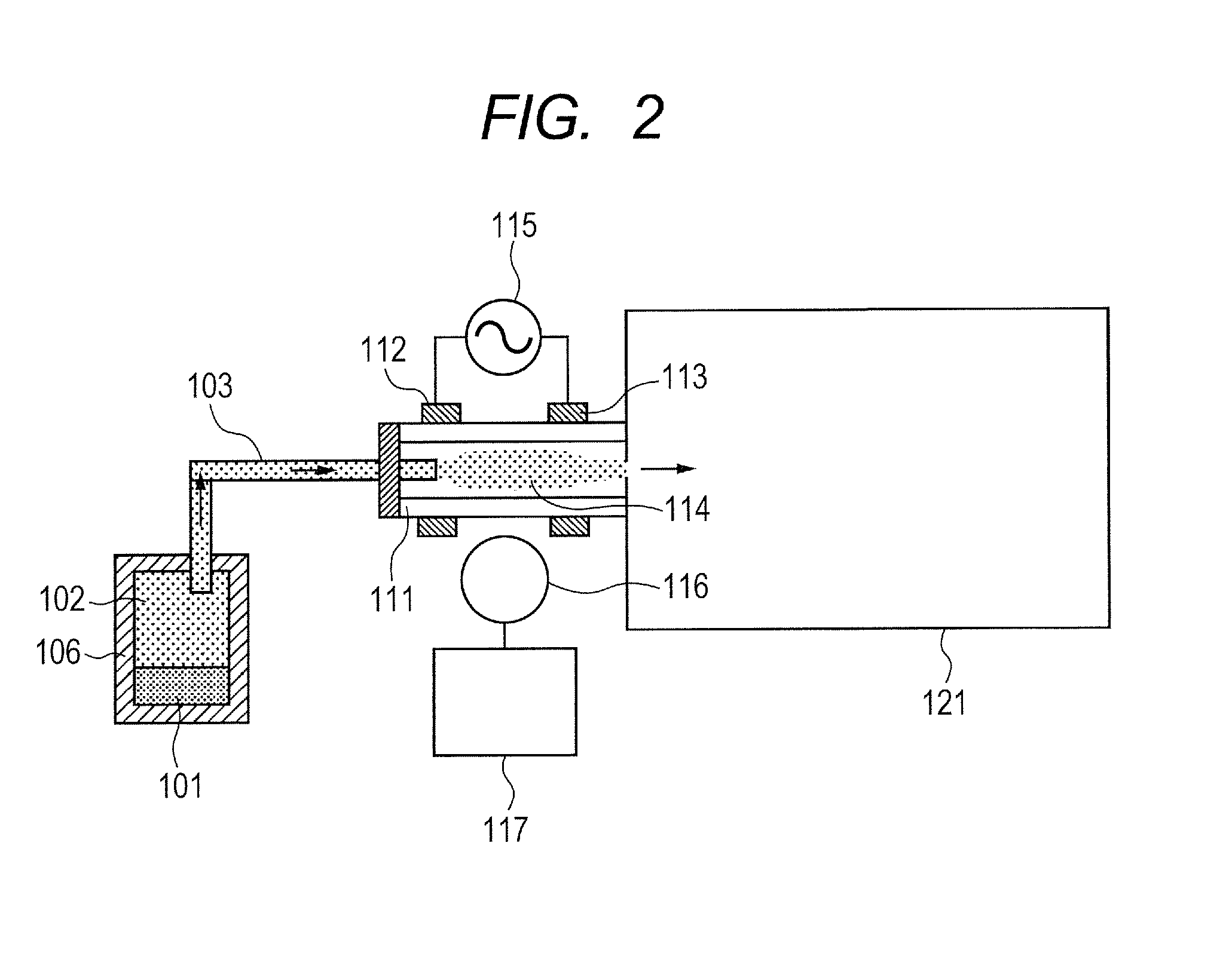
[0052]FIG. 9 shows an embodiment in a case of continuously introducing a sample. Although a basic configuration of Second Embodiment is the same as that of First Embodiment (FIG. 1), there are not the cover, the valve and the valve opening / closing control mechanism. The sample 101 is introduced to the ion source unit along with the discharge gas by the pressure difference produced by the vacuum pump installed at the mass spectrometry and ion detecting unit 121. According to the example, air is continuously introduced as a discharge gas by opening the sample vessel to 106 to the atmosphere. Therefore, a mechanism of supplying the discharge gas of a gas bomb or the like is not needed. However, an ion or a radial generated by a plasma differs by a discharge gas, and therefore, a mechanism of introducing a gas of helium, argon, nitrogen or the like as a discharge gas may be installed as necessary. 9a, 9b, or 9c in the drawing is conceivable as a location of installing a gas introducing ...
third embodiment
[0056]FIG. 11 shows an example of installing a light source at an inner portion of an ion source. A configuration of an ion source unit differs from that of First Embodiment (FIG. 1). At the ion source, a dielectric barrier discharge is generated at the discharge area 114 by using an electrode 162 for discharge covered by a dielectric 161, a discharge electrode 163, and the alternating current power source 115. Even in a case where only one of the electrodes on the side of the discharge area is covered with the dielectric 161 as in FIG. 11, a low temperature plasma in which fragmentation of the sample is inconsiderable can be generated. An expense necessary for the dielectric can be reduced by reducing an amount of using the dielectric.
[0057]Although the illumination is installed at the inner portion of the ion source in this example, a dielectric which does not transmit light can be used since it is not necessary to transmit light therethrough. A quantity of light can be increased ...
PUM
 Abstract
Description
Claims
Application Information