

Method of navigating in a virtual three-dimensional environment and an electronic device employing such method
- Summary
- Abstract
- Description
- Claims
- Application Information
AI Technical Summary
Benefits of technology
Problems solved by technology
Method used
Image

Examples
first embodiment
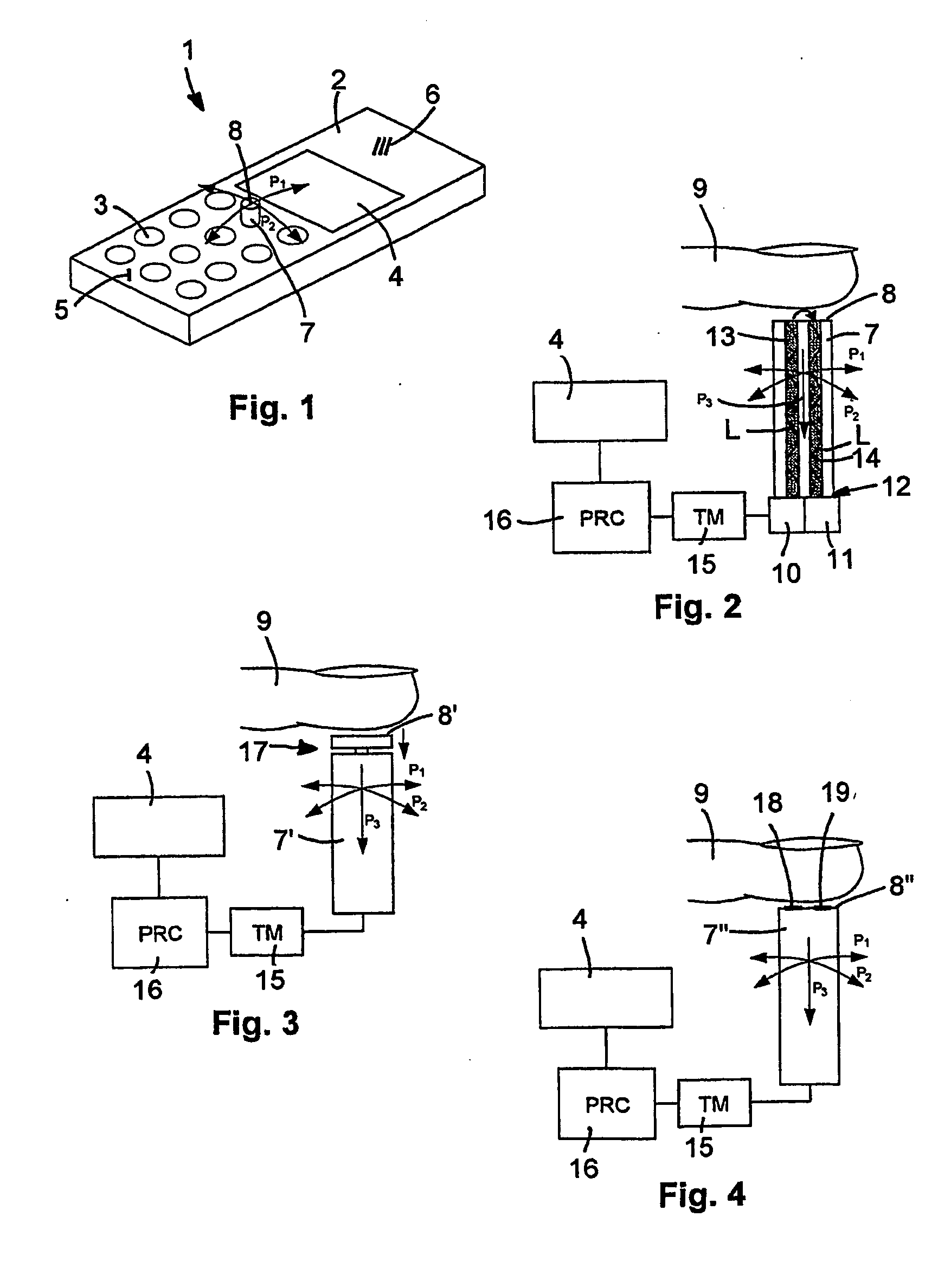
[0031]FIG. 2 shows schematically a movable physical member 7. The movable physical member 7 is rod-shaped and Is connected to the electronic device, such as the mobile telephone 1 shown in FIG. 1, in a commonly known manner that will not be described in detail. A person skilled in the art of electronic devices can easily provide such connection.
[0032] As mentioned above with reference to FIG. 1, the movable physical member 7 is provided with a user surface 8 to which a finger 9 may be applied and is arranged to be tiltable in the directions of the double arrows P1 and P2. The movable physical member 7 is also depressable in direction of the arrow P3. A movable physical member 7 arranged in this manner is generally known in the art.
[0033] Apart from the provisions described above, the movable physical member 7 is provided with sensing means for sensing if a finger is applied to the user surface 8 of the movable physical member 7. In the first embodiment shown in FIG. 2 the sensing m...
second embodiment
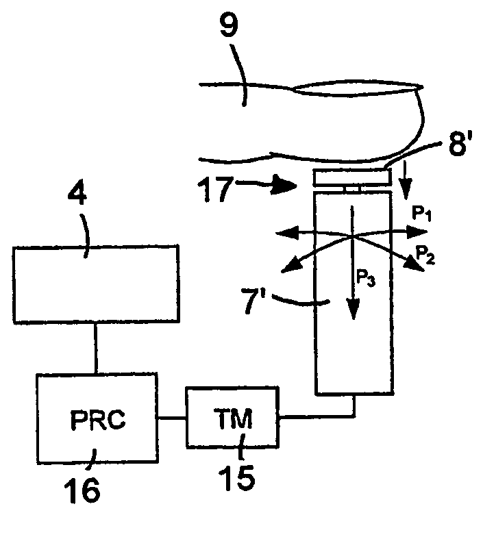
[0037] a movable physical member 7′ provided in an electronic device according to the invention is shown in FIG. 3. This movable physical member 7′ is also movable in the directions of the double arrows P1 and P2 as well as being depressable in the direction of the arrow P3. The movable physical member 7′ is provided with a user surface 8′ that is a part of a micro switch 17 that is circuited whenever a finger 9 is applied to the user surface 8′ of the movable physical member 7′. The micro switch 17 is very sensitive and will always be circuited when a finger 9 is applied to the user surface 8′.
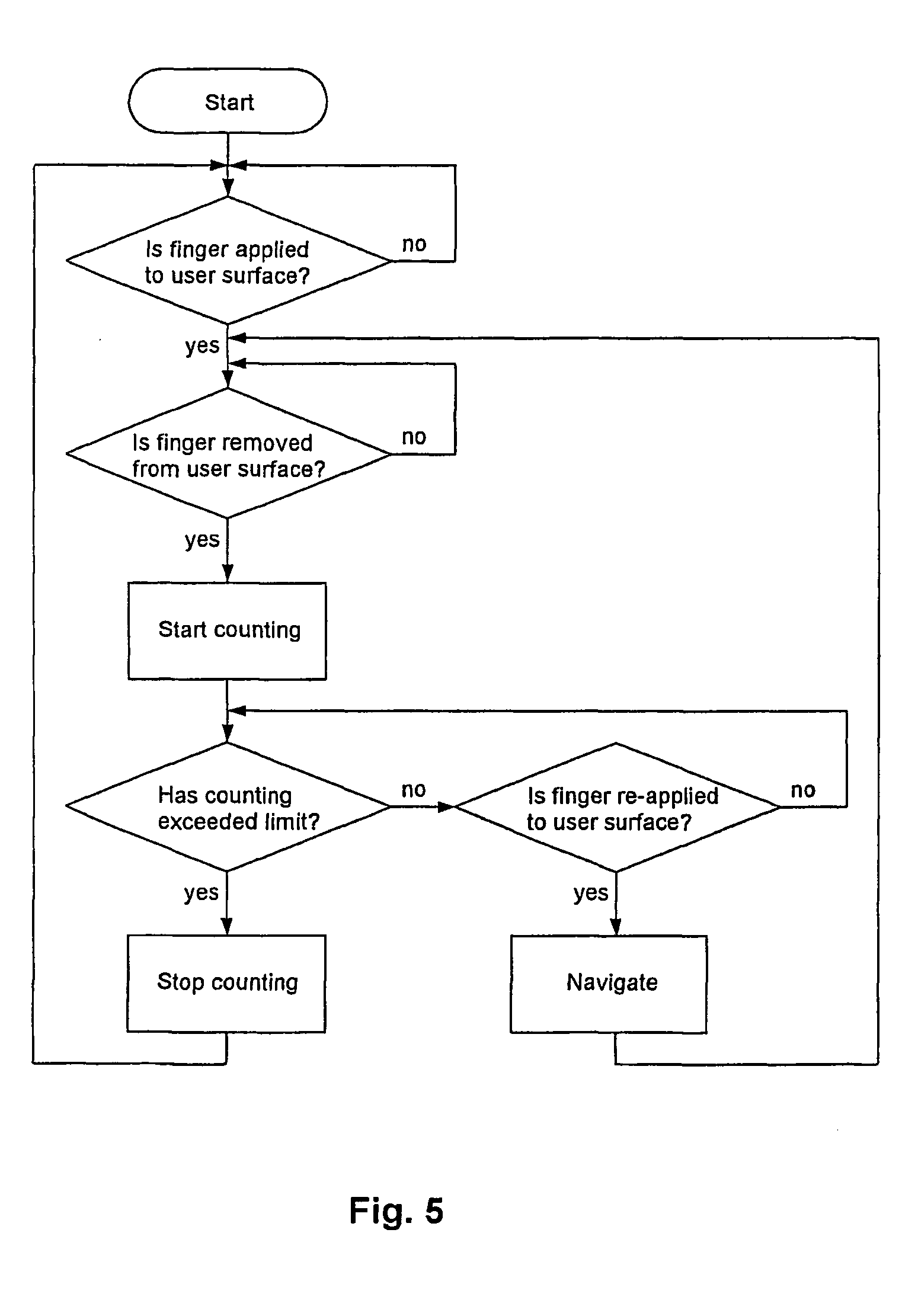
[0038] This movable physical member 7′ is also connected to a timer 15 that starts counting when the finger 9 is removed from the user surface 8′, i.e. when the micro switch 17 is released, and stops when the finger 9 is re-applied to the user surface 8′, i.e. when the micro switch 17 is circuited again. The relation and structure of the timer 15, the processor 16 and the display 4 are as des...
third embodiment
[0039] a movable physical member 7″ provided in an electronic device according to the invention is shown in FIG. 4. This movable physical member 7″ is also movable in the directions of the double arrows P1 and P2 as well as being depressable in the direction of the arrow P3. The movable physical member 7″ is provided with a user surface 8″ that is provided with two conducting plates 18,19 that are short-circuited when a finger 9 is applied to the user surface 8″. Such resistive and / or capacitive coupling is a commonly known technique in which application of a finger 9 to the user surface 8″ is detectable in a simple and reliable manner.
[0040] This movable physical member 7″ is also connected to a timer 15 that starts counting when the finger 9 is removed from the user surface 8″, i.e. when the two conducting plates 18,19 are no longer short-circuited, and stops when the finger 9 is re-applied to the user surface 8′, i.e. when the two conducting plates 18,19 are short-circuited again...
PUM
 Abstract
Description
Claims
Application Information