Lens shading algorithm

a shading algorithm and lens technology, applied in the field of image processing, can solve the problems of unworkable, inacceptable, and inability to use typical complex optical systems, and achieve the effect of fast and efficient calculation

Active Publication Date: 2005-08-18
GULA CONSULTING LLC
View PDF3 Cites 37 Cited by
  • Summary
  • Abstract
  • Description
  • Claims
  • Application Information

AI Technical Summary

Benefits of technology

[0016] A principal object of the present invention is to achieve a fast and efficient way to calculate correction values to compensate vignetting in digital cameras.

Problems solved by technology

All camera lenses suffer, more or less, of these optical phenomena.
Obviously the last case is unworkable and is not acceptable.
In order to solve said problems with lens shading, cameras are using typically complex optical systems, which are very expensive to manufacture.
It is a challenge for the designers of digital cameras to design a camera having very low vignetting using less expensive lenses.

Method used


Image

  • Lens shading algorithm
  • Lens shading algorithm
  • Lens shading algorithm

Examples


Embodiment Construction

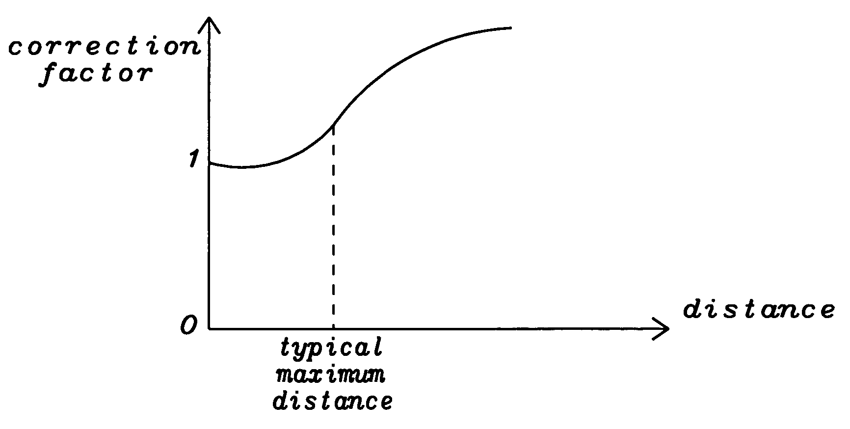
[0027] The preferred embodiments disclose a novel algorithm and a method to compute a correction factor to compensate lens shading or vignetting of digital cameras allowing the usage of a cheaper lens and still producing a high image quality in respect of vignetting. Said algorithm of the present invention can be can computed in a very fast and efficient way and consumes less power and time for tits computation. A correction factor is calculated for each pixel of the sensor used.

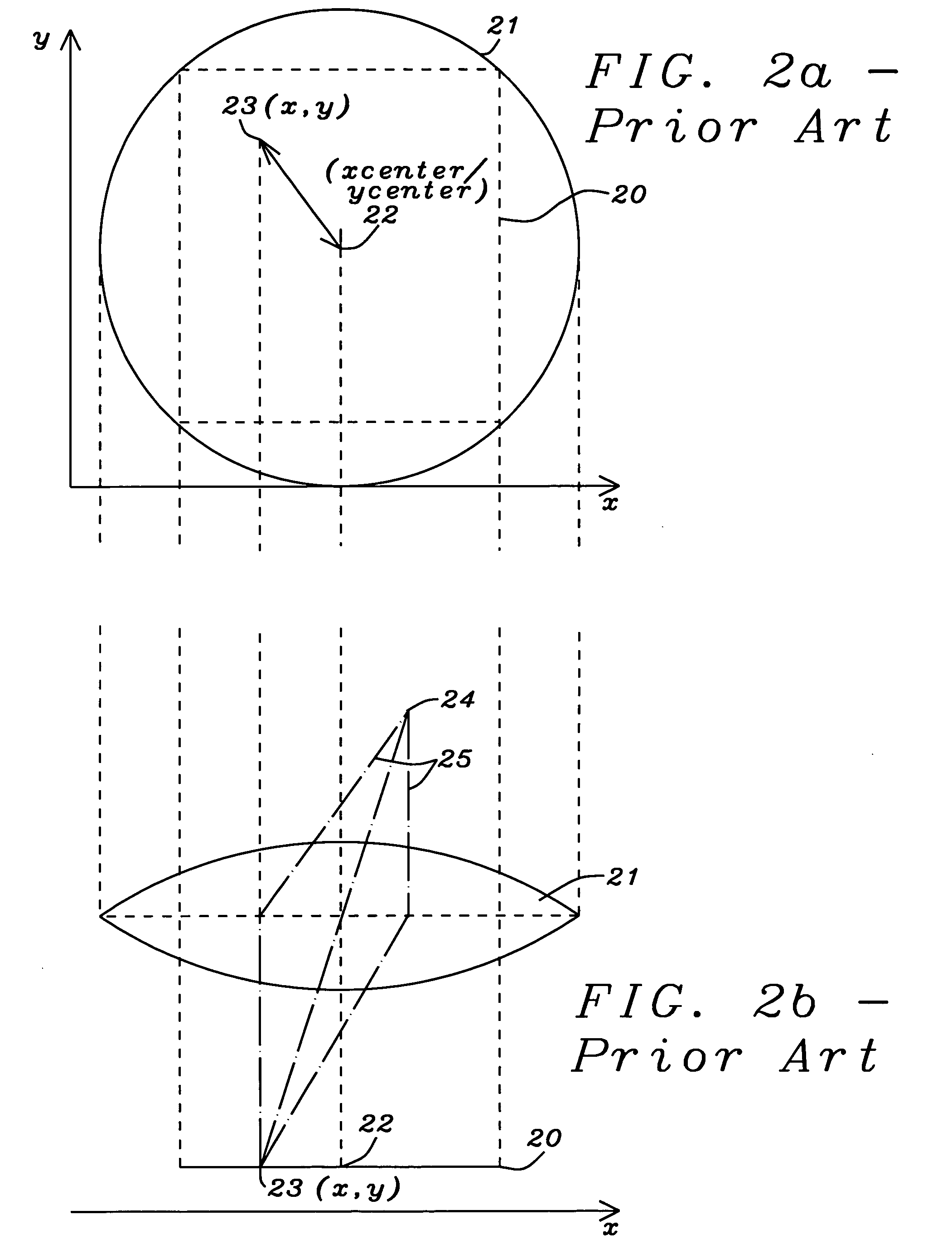
[0028] At first for each pixel the square dist2 of its distance from the center of the image array (as shown in FIGS. 2a and 2b prior art) has to be calculated:

dist2(x,y)=(x−xcenter)2+(y−ycenter)2,  (3)

wherein X and y are the coordinates of a pixel and Xcenter and Ycenter are the coordinates of the center of an image array corresponding to the center of the lens used. The next step ids the calculation of the square dist4 of this squared distance dist2 has to be calculated:

dist4(x,y)=(dist2)2.  (4)

[0029...


PUM


Abstract

A method used for the compensation of vignetting in digital cameras has been achieved. The compensation for vignetting is performed by multiplying pixel output of the sensor array with a correction factor. In a preferred embodiment of the invention all pixels are multiplied with an adequate correction factor. Alternatively pixels, being close to the center of the sensor array, can be left unchanged. Said correction factor can be calculated in a very fast and efficient way by using two constant factors describing the specific geometry of the lens / sensor array system and by multiplying a first of said factors with the square of the distance between a pixel and the center of the sensor array and by multiplying a second of said factors with the distance between a pixel and the center of the sensor array to the power of four. The result of the second multiplication is subtracted from the result of the first multiplication and this result is added to one to get the final correction factor. Each original pixel output is multiplied with said correction factor to get output data compensated for the vignetting effects of the lens.

Description

RELATED PATENT APPLICATION [0001] This application is related to U.S. patent application Ser. No. 10 / 379,863, filed on Mar. 4, 2003, and assigned to the same assignee as the present invention.BACKGROUND OF THE INVENTION [0002] (1) Field of the Invention [0003] This invention relates generally to image processing and relates more particularly to a method and an algorithm to compensate lens shading or vignetting in digital images. [0004] (2) Description of the Prior Art [0005] Photographically, vignetting means the darkening of the corners relative to the centre of an image. All camera lenses suffer, more or less, of these optical phenomena. [0006]FIG. 1 prior art describes some major steps performed in image processing. In the first step 10 a raw image is obtained. In the next step 1 the offset / gain calibration is performed, followed by the compensation for vignetting 12. The last step 13 is the color processing. [0007] A simple lens obeys an optical law called the “cos-4th law” (cos...

Claims


Application Information

Patent Timeline
Patent Type & Authority Applications(United States)
IPC IPC(8): G01J5/02G06T5/00H04N5/217H04N9/64
CPCH04N5/217H04N1/401H04N5/3572G06T5/008H04N23/81H04N25/61G06T5/94
Inventor SCHWENG, DETLEF
Owner GULA CONSULTING LLC
Why Eureka
Try Eureka