Method, apparatus and program for detecting an object

Active Publication Date: 2005-08-18
HONDA MOTOR CO LTD
View PDF5 Cites 20 Cited by
  • Summary
  • Abstract
  • Description
  • Claims
  • Application Information

AI Technical Summary

Benefits of technology

[0007] The advantage of the present invention is to provide a process that is simple and less dependent on the observing place in order to appropriately detect the object.
[0008] The present invention uses the three-dimensional characteristics of objects in the determination of their shapes. This determination is completely different from the contour based detection since the contour detection uses two-dimensional characteristics of the objects. The present invention uses the image of the object which provides a portion of object and image is combined with the distance information wherein the distance is defined by that from the image acquiring cameras to the object. Therefore the portion of the object can be evaluated with the possible portion of the object which represents the two dimensional information of the object and with the possible position (actually the distance from the cameras) which represents the third dimensional information of the object. The combination of the portion information and the position information is evaluated by the probability so that the object is determined with such three dimensional information. For this process, the portion information in the two dimensional data and distance information are all the observed ones and have effectively self-determinative so that no large computation is required like as the conventional contour method such as SNAKES.
[0009] The object detection apparatus regarding the present invention has a plurality of cameras to determine the di

Problems solved by technology

However, it requires a lot of computation power for the purpose

Method used


Image

  • Method, apparatus and program for detecting an object
  • Method, apparatus and program for detecting an object
  • Method, apparatus and program for detecting an object

Examples


Embodiment Construction

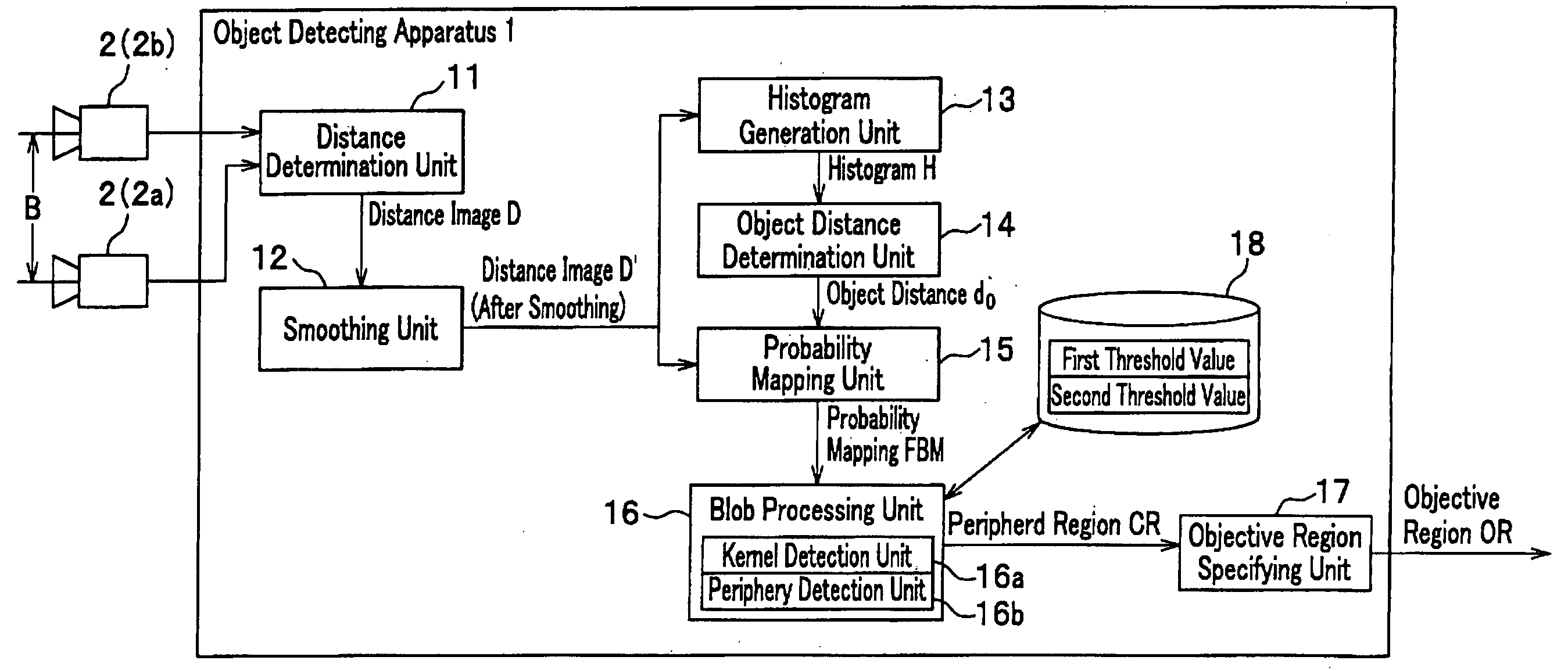
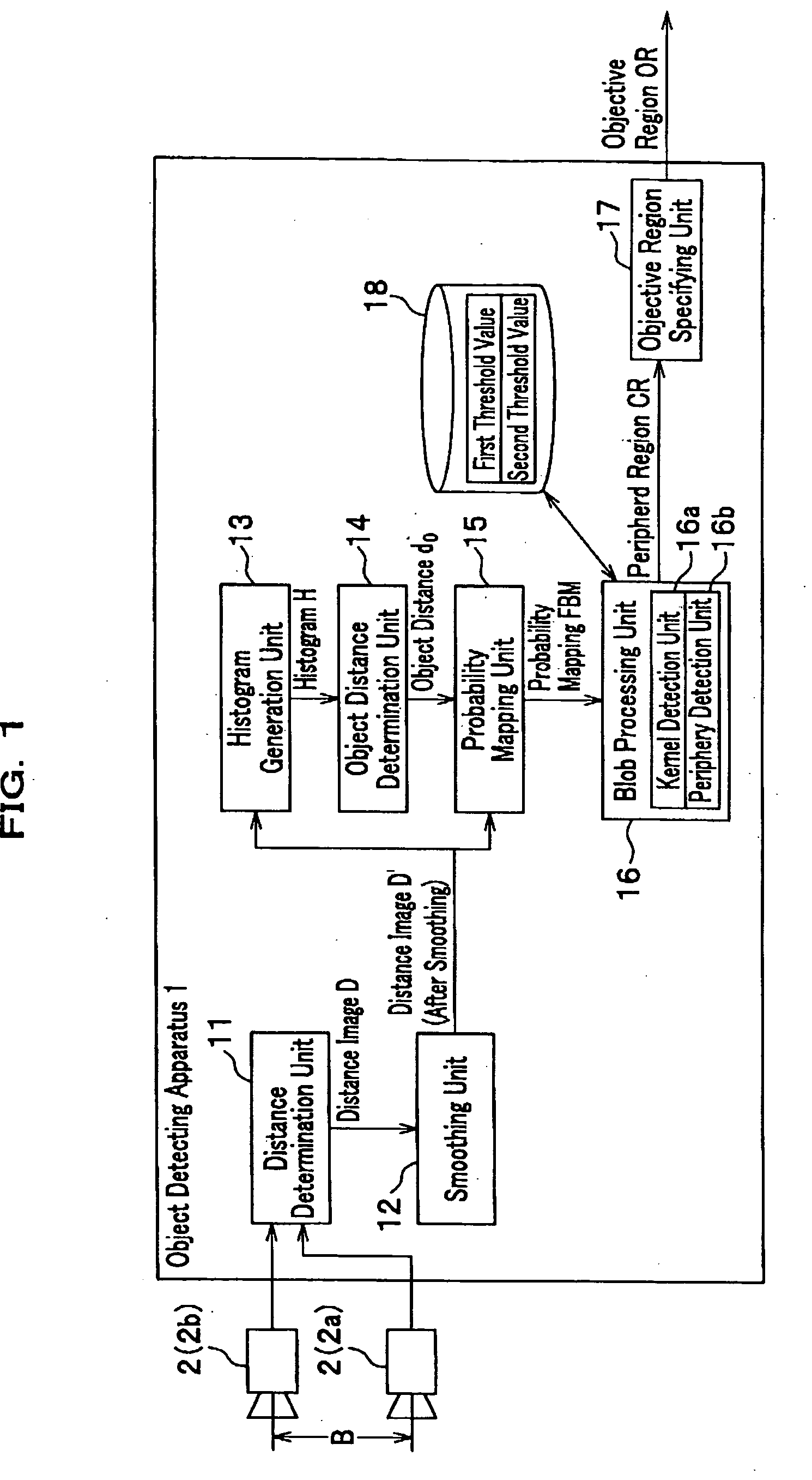
[0028] The object detection apparatus in the present invention has a plurality of cameras to determine the distance to the objects by using the parallax, a distance determination unit to determine the distance therein, a histogram generation unit to specify the frequency of the pixels in the portion of the image taken by the cameras against the distances to the pixels, the object distance determination unit that determines the likely distance where the quantity of the pixels has the maximum in the histogram, a probability mapping unit that generates a map of the probability values of the pixels based on the difference of the distance from the most likely distance obtained by the object distance determination unit, a kernel detection unit that determines a kernel region as a group of the pixels which have the probabilities more than the first threshold value, periphery detection unit that determines a peripheral region as a group of the pixels, selected from the pixels being close to...


PUM


Abstract

The advantage of the present invention is to appropriately detect the object. The object detection apparatus in the present invention has a plurality of cameras to determine the distance to the objects, a distance determination unit to determine the distance therein, a histogram generation unit to specify the frequency of the pixels against the distances to the pixels, an object distance determination unit that determines the most likely distance, a probability mapping unit that provides the probabilities of the pixels based on the difference of the distance, a kernel detection unit that determines a kernel region as a group of the pixels, a periphery detection unit that determines a peripheral region as a group of the pixels, selected from the pixels being close to the kernel region and an object specifying unit that specifies the object region where the object is present with a predetermined probability.

Description

RELATED APPLICATIONS [0001] This application claims the benefit of U.S. Provisional Patent Application No. 60 / 545,759, filed Feb. 17, 2004, and U.S. patent application Ser. No. ______ entitled “Face Recognition System” filed on Jun. 1, 2004 (attorney reference number 23085-09092) which are both incorporated by reference in their entirety.BACKGROUND OF THE INVENTION [0002] 1. Field of the Invention [0003] The present invention relates to an apparatus, a method and a computer program to carry out the detection of the objects, primarily the detection of the object images taken by the cameras included therein and the detection of the objects in is the application. The present invention particularly has an advantage to provide the apparatus, the method and the computer program that realize a simple but a precise visual detection of the objects and the object images. [0004] 2. Background of the Invention [0005] There is a well-known technology called SNAKES for determining a contour of an...

Claims


Application Information

Patent Timeline
IPC IPC(8): G06K9/00G06K9/36G06K9/48
CPCG06K9/00201G06V20/64
Inventor YANG, MING-HSUANLIM, JONGWOOROSS, DAVIDOHASHI, TAKAHIRO
Owner HONDA MOTOR CO LTD
Why Eureka
Try Eureka