Clock and Data Recovery Circuit and Parallel Output Circuit

a clock and data recovery and parallel output technology, applied in the field of data communication, can solve the problems of high high complexity, and inability to meet high-speed situations, and achieve the effect of low jitter of the recovered clock

Active Publication Date: 2013-06-27
LONTIUM SEMICON CORP
View PDF6 Cites 18 Cited by
  • Summary
  • Abstract
  • Description
  • Claims
  • Application Information

AI Technical Summary

Benefits of technology

[0036]As can be seen from the above technical solution, the CDR circuit according to the embodiments of the present invention performs spaced sampling on the input serial data using the n clocks provided by the n-phase clock, performs edge detection and resampling on the sampled data, filters the resampled data by the counting units, obtains the positions of the edges of the serial data according to the counting result of the counting units, selects a clock from the n clocks that is the farthest away from the edges as the recovered clock, and then obtains the recovered data according to the recovered clock. It can be seen that, according to the embodiments of the present invention, the recovered clock is obtained using the n-phase clock, without extracting a clock at each occurrence of the edge of the serial data. Therefore, the CDR circuit according to the embodiments is less dependent on the serial data, and the jitter of the recovered clock is low even when the jitter of the serial data is high.

Problems solved by technology

This type of CDR circuits must guarantee the stability of the closed-loop behavior, thus resulting in high complexity; moreover, the closed-loop structure is not suitable for high-speed situations.
When the jitter of the serial data is high, the jitter of the recovered clock will be high; and in some cases, this may cause faults in the recovered clock, and bit errors.

Method used


Image

  • Clock and Data Recovery Circuit and Parallel Output Circuit
  • Clock and Data Recovery Circuit and Parallel Output Circuit
  • Clock and Data Recovery Circuit and Parallel Output Circuit

Examples


first embodiment

[0050

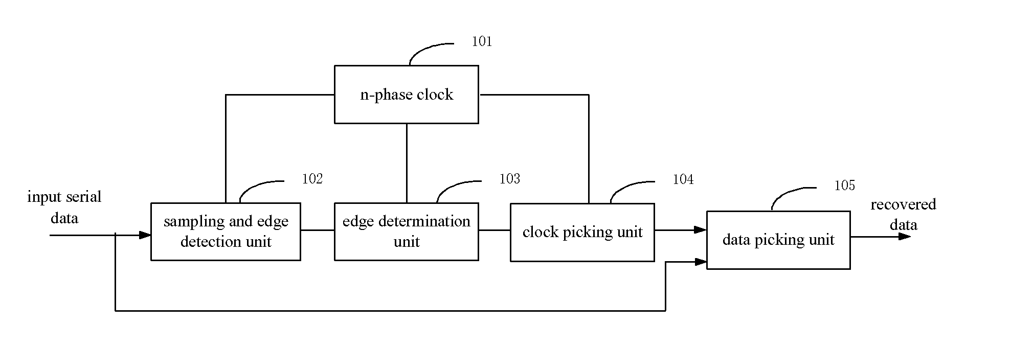
[0051]As shown in FIG. 1, an embodiment of the present invention provides a CDR circuit. In the embodiment, the circuit includes: an n-phase clock 101, a sampling and edge detection unit 102, an edge determination unit 103, a clock picking unit 104 and a data picking unit 105. Specifically, the rate ratio of input serial data to any of the clock signals provided by the n-phase clock is m. When m=1, the rates of the input serial data and the n-phase clock are the same, and the n-phase clock operates in a full-rate mode. Generally, the n-phase clock may also operate in a 1 / m rate mode, e.g., ½, ⅓ or ¼; hence m is a natural number greater than zero. In the embodiment, the n-phase clock is used for spaced sampling of the input serial data, with n / m being a sampling accuracy. In order to satisfy the sampling theorem, n / m must be a natural number greater than 2, and it is clear that n is an integer multiple of m.

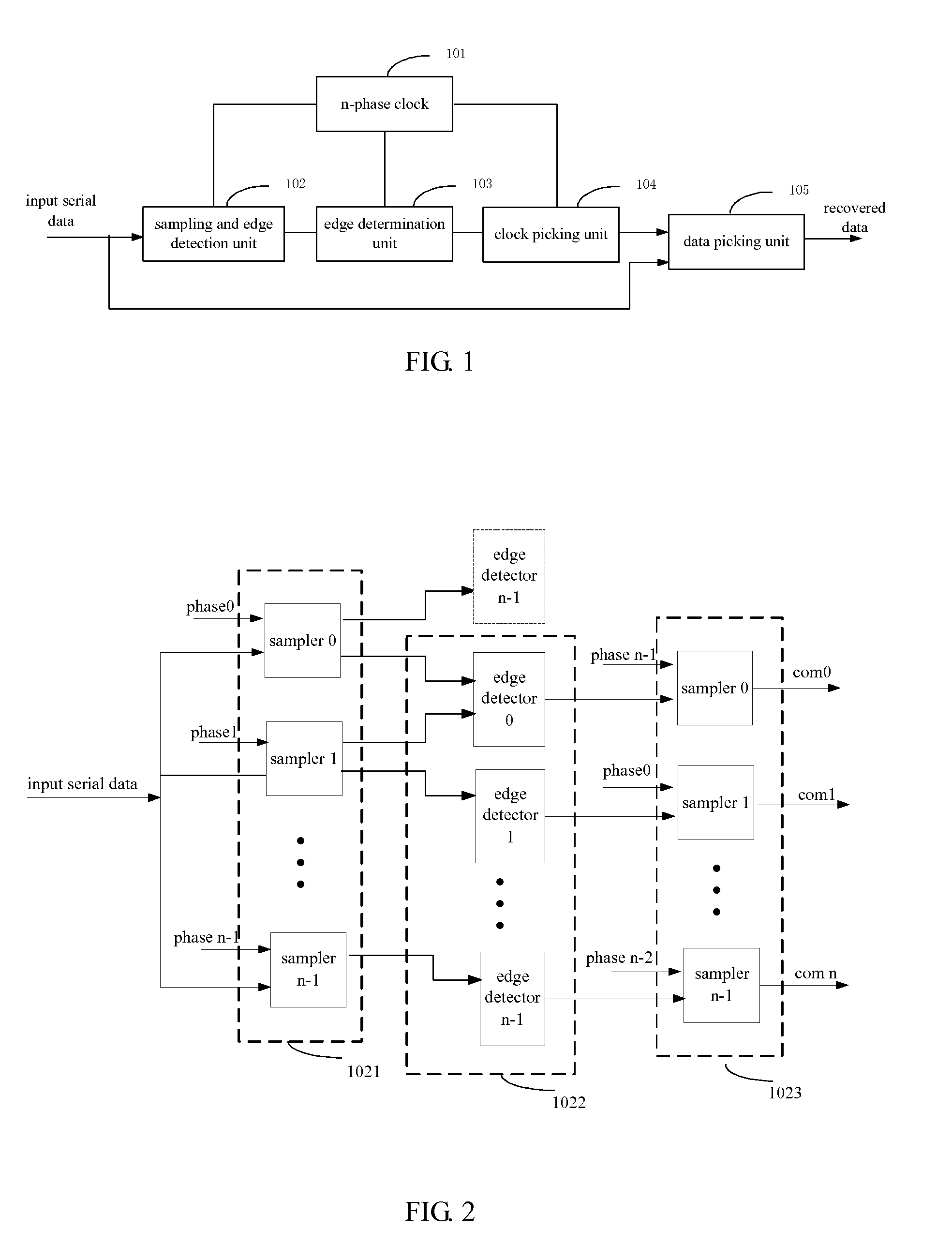
[0052]As shown in FIG. 2, the sampling and edge detection unit 102 in th...

second embodiment

[0079

[0080]A CDR circuit in accordance with another embodiment of the present invention is illustrated in FIG. 5. In the embodiment, the circuit includes: an n-phase clock 101, a sampling and edge detection unit 102, an edge determination unit 501, a clock picking unit 502 and a data picking unit 503. Specifically, m=1, in other words, the rates of the input serial data and the n-phase clock are the same, i.e., the n-phase clock is in a full-rate mode.

[0081]The sampling and edge detection unit 102 may have the same structure and functions as those of the sampling and edge detection unit 102 in the first embodiment as shown in FIG. 2. Detailed description is thus omitted.

[0082]In the embodiment, the edge determination unit 501 includes n counting units. A k-th counting unit is used to count the sampled edge information from a k-th sampler in the second sampling group, using a k-th or (k+1)-th clock provided by the n-phase clock. When a counting value of an s-th counting unit of the n...

third embodiment

[0087

[0088]A CDR circuit in accordance with yet another embodiment of the present invention is illustrated in FIG. 8. In the embodiment, the circuit includes: an n-phase clock 101, a sampling and edge detection unit 102, an edge determination unit 103, a clock picking unit 104, a path matching unit 801 and a data picking unit 802.

[0089]The n-phase clock 101, the sampling and edge detection unit 102, the edge determination unit 103 and the clock picking unit 104 may have the same structure and functions as those of the sampling and edge detection unit 102 in the first embodiment. Detailed description is thus omitted.

[0090]The input serial data are input to the path matching unit 801. The time delay of the path matching unit 801 must be the same as the clock picking unit 104. Specifically, the logic devices used in the path matching circuit may be consistent with those of the clock picking unit, thereby eliminating the need to adjust the time delay of the path matching circuit.

[0091]T...


PUM


Abstract

The present invention provides a clock and data recovery circuit, including an n-phase clock, a sampling and edge detection unit, an edge determination unit, a clock picking unit and a data picking unit. The sampling and edge detection unit performs spaced sampling on the input serial data using the n-phase clock, and performs edge detection and resampling on the sampled data. The edge determination unit filters the resampled data by the counting units, and obtains the positions of the edges of the serial data according to the counting result of the counting units. The clock picking unit selects a clock from the n clocks that is the farthest away from the edges as the recovered clock. The data picking unit obtains the recovered data according to the recovered clock. The present invention also provides a parallel output circuit.

Description

[0001]This application claims the benefit of Chinese patent application No.201210504519.4 titled “CLOCK AND DATA RECOVERY CIRCUIT AND PARALLEL OUTPUT CIRCUIT” and filed with the State Intellectual Property Office on Nov. 30, 2012, and claims the benefit of Chinese patent application No.201110444863.4 titled “SERIAL CLOCK AND DATA RECOVERY CIRCUIT FOR USB 2.0 HI-SPEED” and filed with the State Intellectual Property Office on Dec. 27, 2011, both of which are incorporated herein by reference in their entireties.FIELD OF THE INVENTION[0002]The present invention relates to the field of data communications, and in particular to a clock and data recovery circuit and a parallel output circuit.BACKGROUND OF THE INVENTION[0003]In serial data transmission, a receiver / transmitter circuit is used for conversion between internal parallel data and external serial data. Specifically, based on the sampling theorem, the transmitter takes the parallel data, realizing parallel-to-serial conversion, sen...

Claims


Application Information

Patent Timeline
Patent Type & Authority Applications(United States)
IPC IPC(8): H04L7/00
CPCH04L7/0338H04L7/0012
Inventor TAI, LIANLIANGLI, GUANGRENCHEN, FENG
Owner LONTIUM SEMICON CORP
Why Eureka
Try Eureka