Sill plate

a technology of soffit and soffit, which is applied in the field of soffit, can solve the problems of general discoloration, odor, and drywall disintegration, and achieve the effects of reducing the number of soffit, and improving the quality of soffi

Inactive Publication Date: 2005-08-25
CONSTR SOLUTIONS
View PDF18 Cites 69 Cited by
  • Summary
  • Abstract
  • Description
  • Claims
  • Application Information

AI Technical Summary

Benefits of technology

[0022] The sill plate may further comprise a second wall extending from the base section and a second shelf associated with the second wall, the second shelf extending along a plane substantially parallel to a plane formed by the base section, the method further comprising supporting a second sheet of drywall on the sec

Problems solved by technology

Mold is problematic for drywall in that it causes staining and general discoloration.
Mold may also cause the drywall to disintegrate over time, or begin to emit an odor.
The formation of certain molds may be a health detriment to individuals exposed to the mold or spores therefrom which may travel away from the spore source, for example, by becoming airborne from forced air heating or cooling.
Thus, mold in any area of a structure may taint the entire structure.
Such health problems may range in minor cases from allergic reactions to actual sicknesses in severe cases.
This method is problematic as it is often difficult to coordinate use of a bent steel wedge with one's foot while simultaneously holding

Method used


Image

  • Sill plate
  • Sill plate
  • Sill plate

Examples


Embodiment Construction

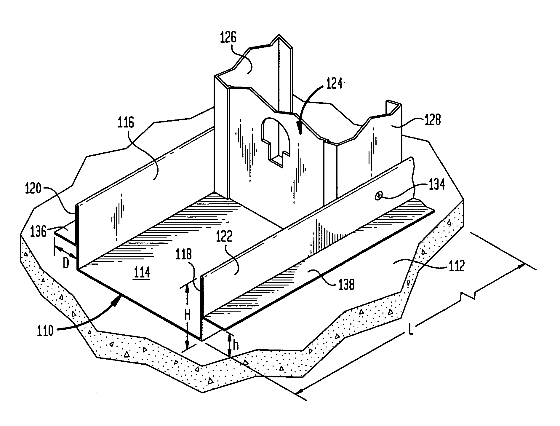
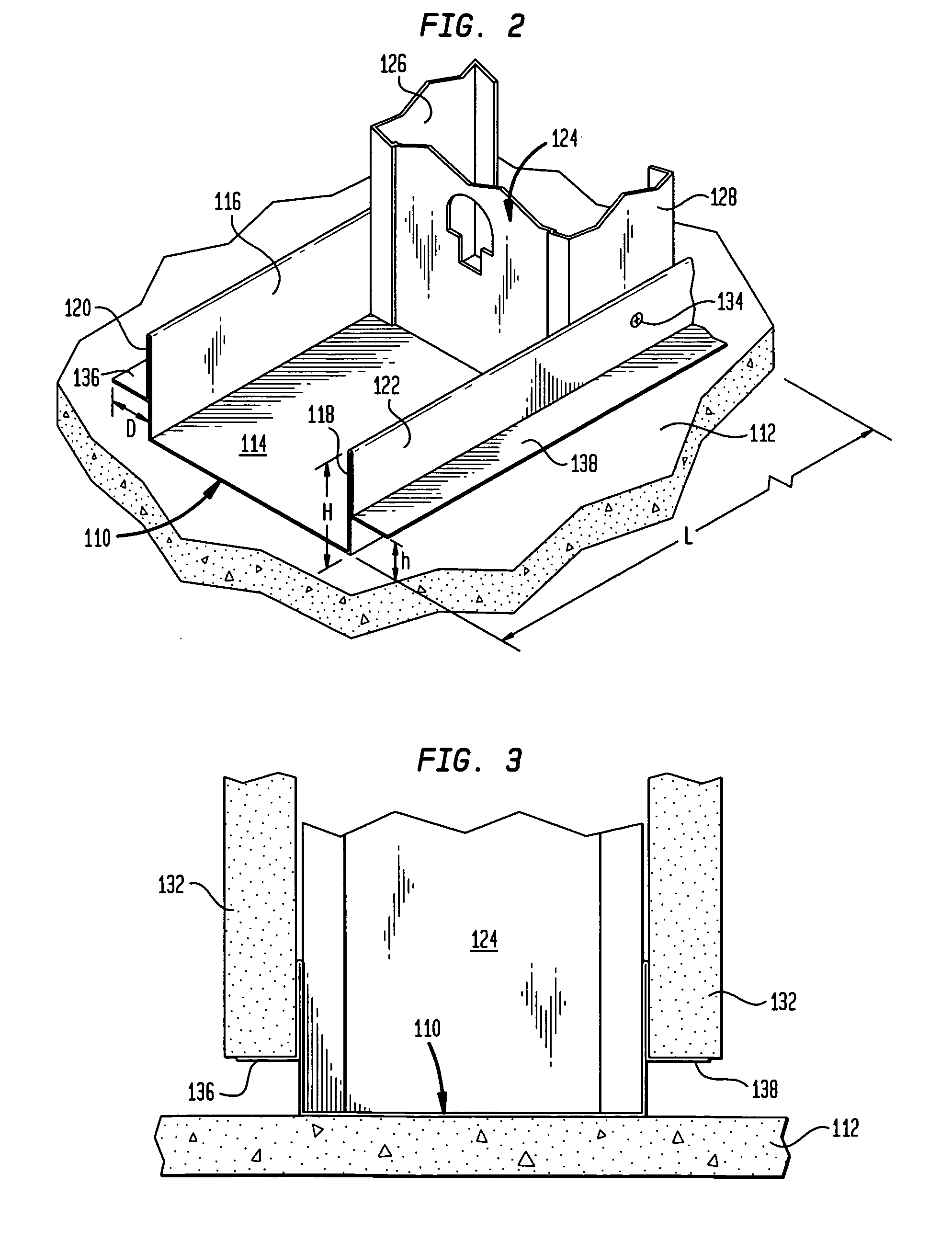
[0031] In the following are described the preferred embodiments of the sill plate in accordance with the present invention. In describing the embodiments illustrated in the drawings, specific terminology will be used for the sake of clarity. However, the invention is not intended to be limited to the specific terms so selected, and it is to be understood that each specific term includes all technical equivalents that operate in a similar manner to accomplish a similar purpose. Where like elements have been depicted in multiple embodiments, identical reference numerals have been used in the multiple embodiments for ease of understanding.

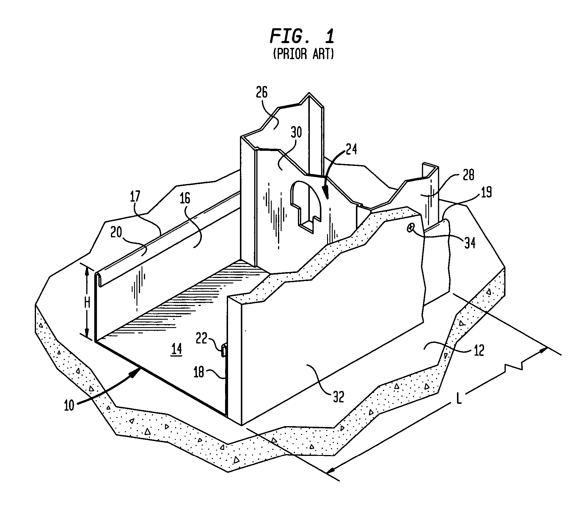
[0032] In this regard, applicant has used the term sill plate extensively throughout this application to describe the underlying inventive structure. The term sill plate is believed to be the preferred terminology throughout the construction industry for describing the lower-most horizontal member of a framing system, or that member of a structural s...


PUM


Abstract

A sill plate adapted to support drywall above a floor surface to prevent the formation of mold in the drywall. The sill plate has a base section and a first wall associated with the base section. A first shelf is associated with the first wall. The first shelf is adapted to support drywall. The sill plate may also include a second wall associated with the base section where the second wall is opposed from the first wall. The second wall may include a second shelf associated with the second wall. Each of the first shelf and second shelf may extend along a plane parallel to a plane passing through the base section. Drywall may rest on the first shelf prior to being affixed to vertical studs extending from the sill plate.

Description

CROSS REFERENCE TO RELATED APPLICATIONS [0001] This application claims the benefit of the filing date of U.S. Provisional Patent Application No. 60 / 543,757 filed Feb. 11, 2004, the disclosure of which is hereby incorporated herein by reference.BACKGROUND OF THE INVENTION [0002] Steel stud framing, such as light or heavy gauge steel framing, is well known and often used in both commercial and residential construction. Such framing is typically utilized to construct interior partition walls and generally consists of sill plates or channels located at the top and bottom of a wall, with studs extending between the channels, much like more traditional wooden sill plates and wooden studs. Both the sill plates and the studs are typically C-shaped or U-shaped. The studs are typically affixed to the channels by mechanical fastening means, such as self-tapping screws. Once all of the electrical and mechanical appurtenances have been installed between the studs, drywall may then be attached to...

Claims


Application Information

Patent Timeline
IPC IPC(8): E02D27/00E04C3/30
CPCE02D27/00
Inventor FREZZA, JOSEPH A.
Owner CONSTR SOLUTIONS
Why Eureka
Try Eureka