Structural reinforcing system components

a structural reinforcement and component technology, applied in the direction of building roofs, foundation engineering, human health protection, etc., can solve the problems of lateral or shear and uplift loads caused by wind, hurricanes and tornadoes, and are difficult to predict in direction, magnitude and frequency

Active Publication Date: 2007-02-08
LAFFERTY III GEORGE A +2
View PDF63 Cites 20 Cited by
  • Summary
  • Abstract
  • Description
  • Claims
  • Application Information

AI Technical Summary

Problems solved by technology

Lateral or shear and uplift loads such as is caused by wind, storms, hurricanes and tornados are difficult to predict in direction, magnitude and frequency.

Method used


Image

  • Structural reinforcing system components
  • Structural reinforcing system components
  • Structural reinforcing system components

Examples


Embodiment Construction

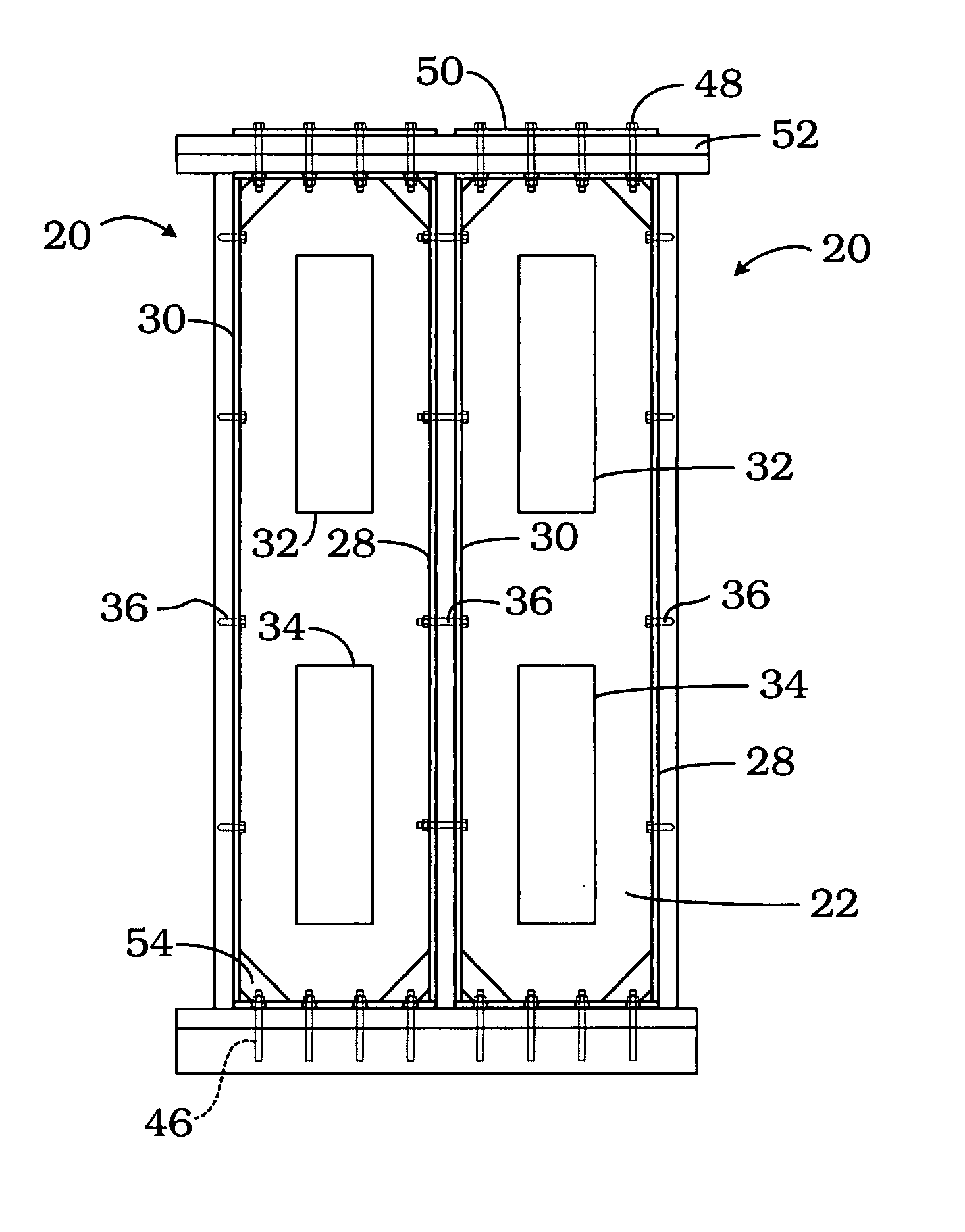
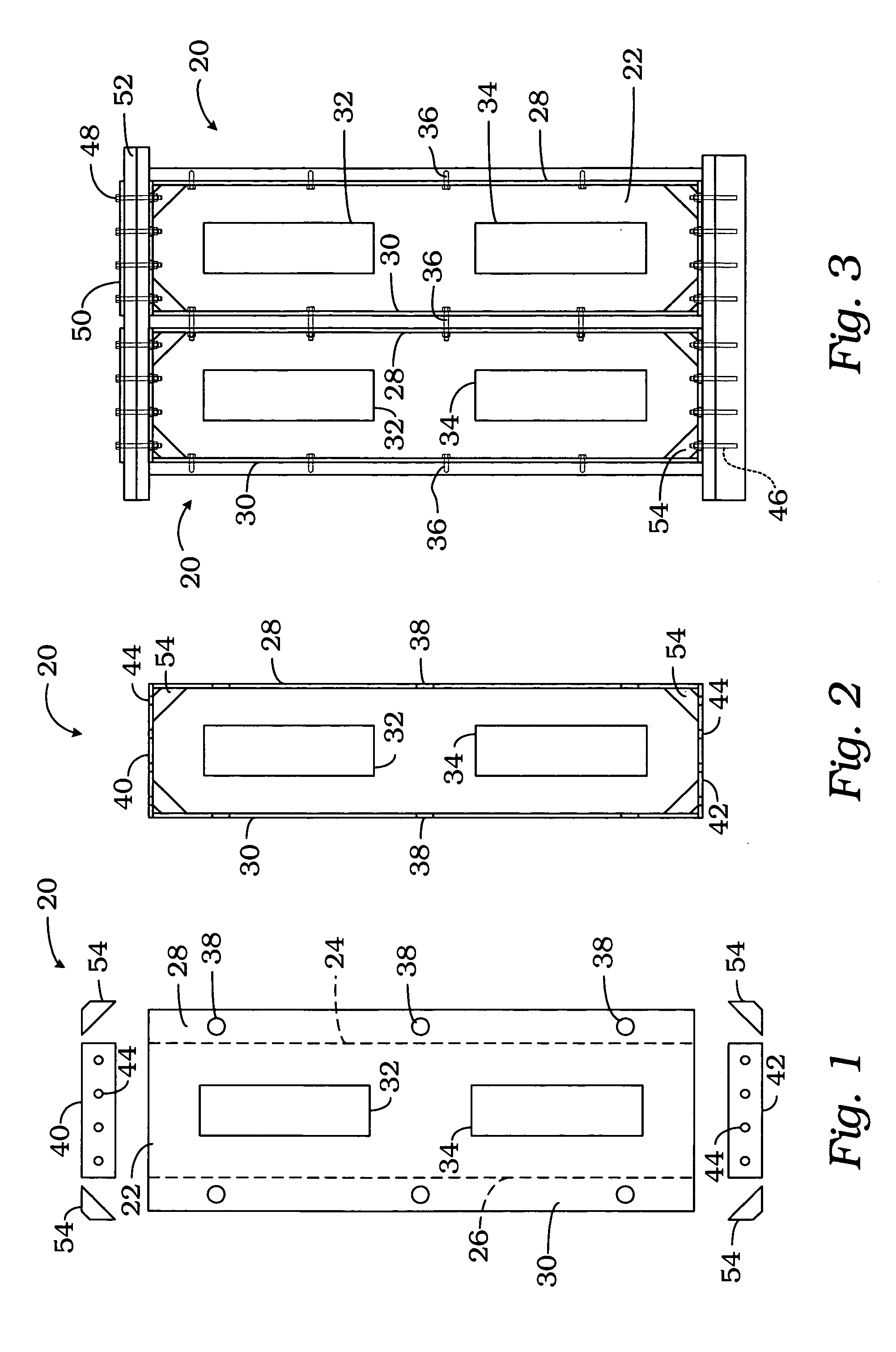
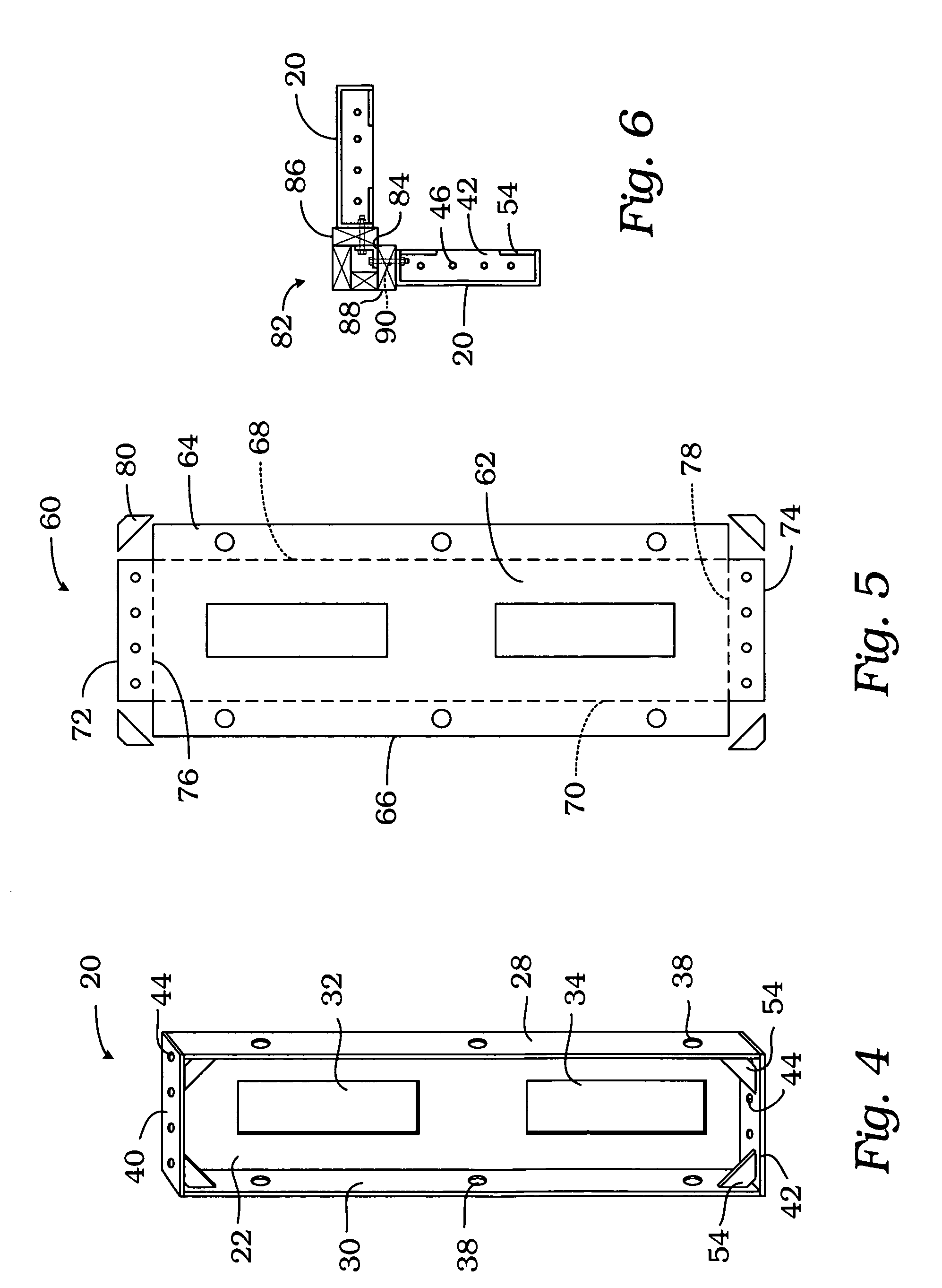
[0021] Referring to FIGS. 1-4, a structural reinforcing panel is generally indicated by reference numeral 20. Structural reinforcing panel 20 may be assembled from the various parts shown in FIG. 1 formed in part from cold or hot rolled steel. Structural reinforcing panel 20 includes a back panel 22 which is folded along lines 24 and 26 to form side panels 28 and 30 to form a tray or channel. The back panel 22 has two cutouts 32 and 34 which reduce the weight of the structural reinforcing panel 20, make it easier to carry, and the removed material can be used to fabricate the additional components.

[0022] The sides 28 and 30 include a plurality of holes (not shown) for fasteners 36 to attach the panel 20 to framing members 38 or to other panels. When attaching to framing members 38, lag bolts may be used, for example. When attaching to other panels 20, a machine bolt and nut may be used. Cut outs 38 are also provided in sides 28 and 30 for mechanical access such as electrical or plu...


PUM


Abstract

A structural reinforcing panel system for reinforcing a structure against lateral or shear and uplift loads. The system includes a structural reinforcing panel which is installed between the studs in a wall of the structure. The panel is connected to the foundation of the structure and the sill or header. Two or more panels may be connected together at a corner, within a wall, ceiling or floor. The roof rafters of the structure may be attached to a top plate bracket mounted to the sill plate, which may also be connected to one or more structural reinforcing panels, provides uplift load support for the structure. For structures built on piers, a pier mount bracket provides a linkage to one or more structural reinforcing panels.

Description

CROSS REFERENCE TO RELATED APPLICATION [0001] This application claims the benefit of a prior filed, co-pending provisional application Ser. No. 60 / 706,195, filed Aug. 5, 2005, entitled STRUCTURAL REINFORCING SYSTEM COMPONENTS.FIELD OF THE INVENTION [0002] The present invention relates to structural components for buildings and, more particularly, to components of a structural reinforcing system for reducing the affects of shear and uplift forces on a building structure. BACKGROUND OF THE INVENTION [0003] The majority of the buildings in the United States are residential or low-rise commercial buildings consisting of a wood frame or light-steel frame structure with wood or composition sheathing. The structure is designed to withstand the anticipated loading conditions such as rain, snow and wind. Forces and loads such as gravity, rain and snow act vertically and typically are generally predictable. Accordingly, structural designs to withstand these forces are readily available. [0004...

Claims


Application Information

Patent Timeline
Patent Type & Authority Applications(United States)
IPC IPC(8): E02D27/00
CPCE04B1/26E04B1/2604E04B7/04E04C2/384E04H9/14E04C2/52E04B2001/2696Y02A50/00
Inventor LAFFERTY, GEORGE A. IIILAFFERTY, RONALD E.MASCAL, DAVID C.
Owner LAFFERTY III GEORGE A
Why Eureka
Try Eureka