Al technical title is built by PatSnap Al team. It summarizes the technical point description of the patent document.
a retainer and plate technology, applied in the direction of snap fasteners, threaded fasteners, screws, etc., can solve the problems of easy trimming, improper seated and secured fasteners to the sheet metal,
Inactive Publication Date: 2007-09-25
NEWFREY
View PDF59 Cites 23 Cited by
Summary
Abstract
Description
Claims
Application Information
AI Technical Summary
This helps you quickly interpret patents by identifying the three key elements:
Problems solved by technology
Method used
Benefits of technology
[0009]In one preferred form, the present invention provides a resilient clip for engaging a dog house coupling feature of a trim component and a mating member for engaging a hole defined in a body panel. The resilient clip includes a body portion having a coupling region, and a triangular mating feature that is positioned relative to the coupling region. The triangular mating feature contacts at least one surface of the dog house structure to prevent rotation of the resilient clip with respect the to the dog house. This reduces rotation of the resilient clip with respect to the hole defined in the body panel. The mating member has a pair of fastening members configured to engage the sides of the mounting hole.
Problems solved by technology
Due to slight misalignments, which can occur between the fasteners and their corresponding mounting holes, some of the fasteners may not be properly seated and secured to the sheet metal.
These seating problems often arise from the rotation of the fastener with respect to a rectangular hole, which essentially prevents the easy fastening of the trim component to the body.
Method used
Image
Click on the blue label to locate the original text in one second.
Reading with bidirectional positioning of images and text.
Examples
Embodiment Construction
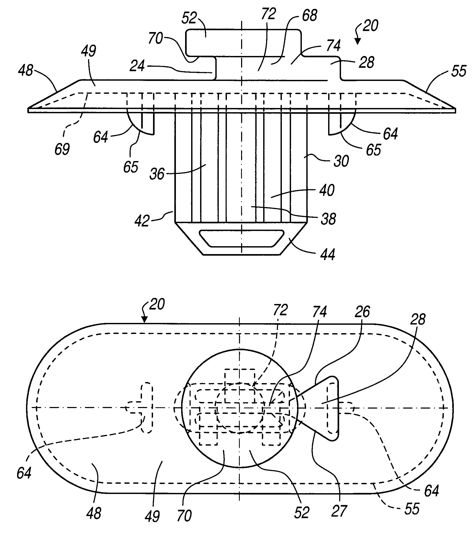
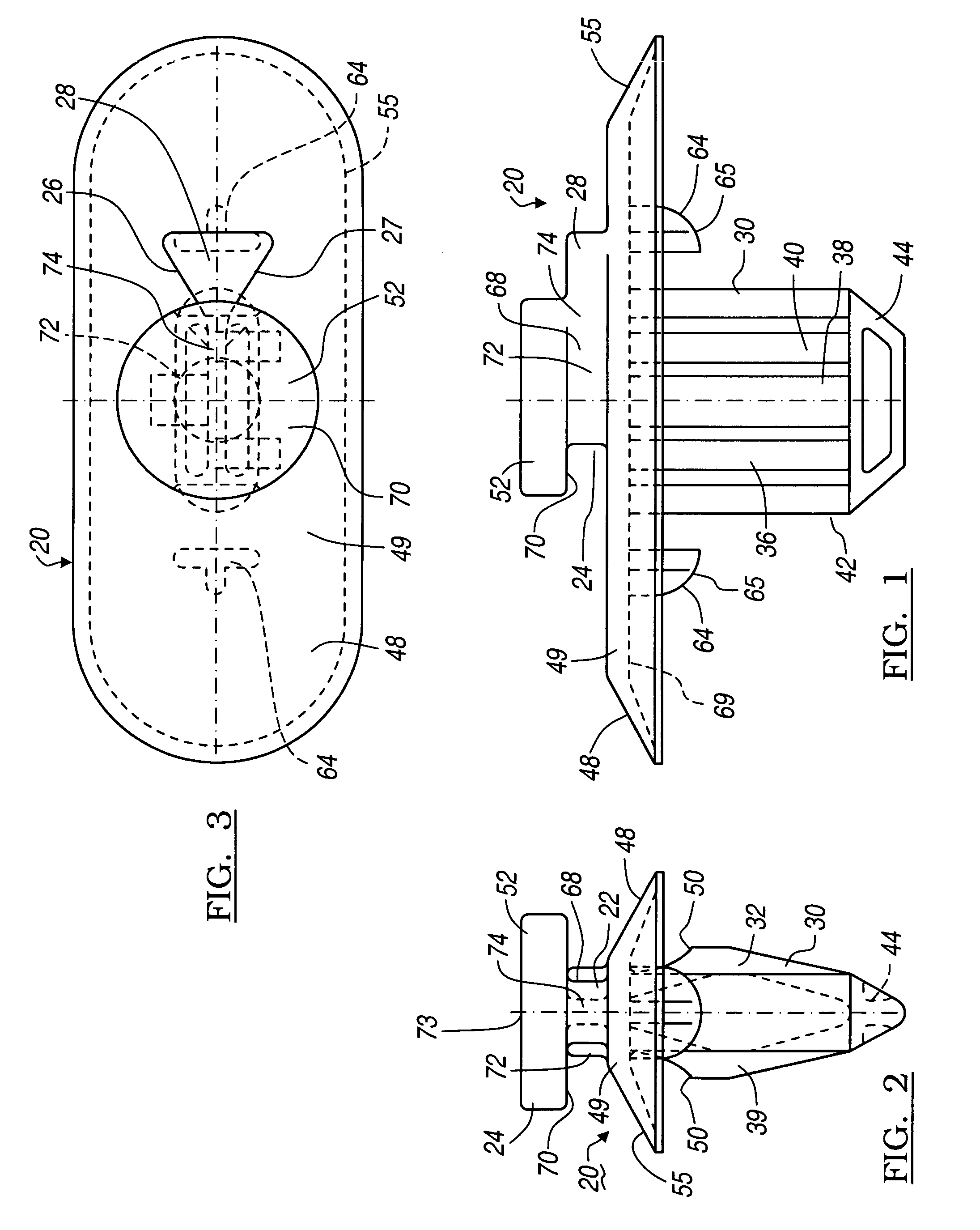
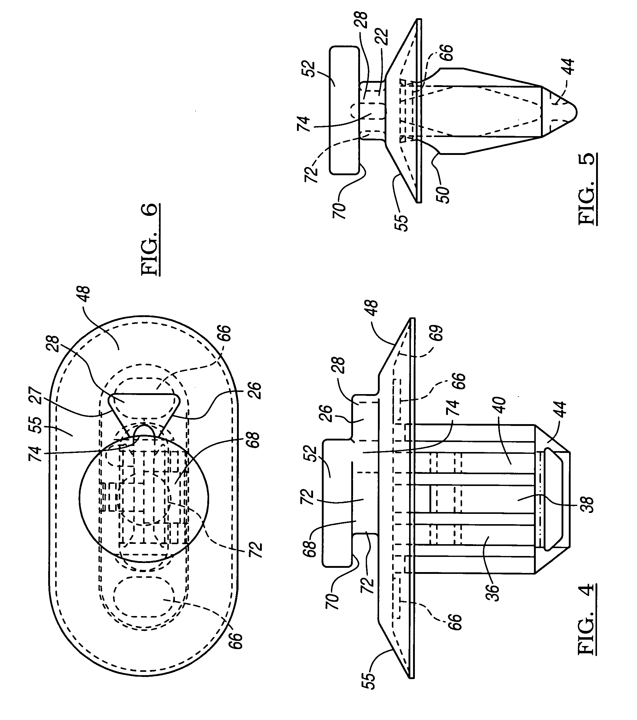
[0020]Referring to FIGS. 1 through 6, a fastener 20 in accordance with the present invention is disclosed. The fastener 20 is defined by a plastic body portion 22 which engages a trim component 23 having a dog house engagement portion 24. Integral with the dog house engagement portion 24 are a pair of engagement surfaces 26 and 27 disposed on abutting flange 28 which are used to engage the mating surfaces 29 of the dog house engagement portion 24. Additionally, the body portion 22 has a mating portion 30 which is formed by two sets 32 and 34 of three locking members 36, 38, 40. The two sets 32 and 34 of three locking members 36, 38, 40 are coupled together at a proximal end 42 by an angled or wedge-shaped member 44. The two sets 32 and 34 of three locking members 36, 38, 40 are coupled together at a distal end 46 by a sealing umbrella portion 48. Each of the three locking members 36, 38, 40 define retaining snap in teeth 50 which facilitate the coupling of the plastic body portion 2...
PUM
Abstract
A resilient clip is provided for engaging a dog house coupling feature of a trim component. The resilient clip has a mating member for engaging a hole defined in a body panel. The resilient clip includes a triangular mating feature that is positioned relative to the coupling region. The triangular mating feature contacts at least one surface of the dog house structure to minimize rotation of the resilient clip with respect the to the dog house. This reduces rotation of the resilient clip with respect to the hole defined in the body panel.
Description
CROSS-REFERENCE TO RELATED APPLICATIONS[0001]This application claims the benefit of U.S. Provisional Application No. 60 / 476,745, filed on Jun. 6, 2003. The disclosure of U.S. Provisional Application No. 60 / 476,745 is incorporated herein by reference. The present application is a continuation-in-part application of prior U.S. patent application Ser. No. 10 / 829,103, filed Apr. 21, 2004, now U.S. Pat. No. 7,186,051 which claims the benefit of U.S. Provisional Application No. 60 / 469,438, filed May 9, 2003. The present application is also a continuation-in-part application of prior U.S. patent application Ser. No. 10 / 842,355, filed May 10, 2004, now U.S. Pat. No. 7,179,013 which claims the benefit of U.S. Provisional Application No. 60 / 474,833, filed May 30, 2003.TECHNICAL FIELD[0002]The present invention relates generally to resilient clip fasteners and more particularly to a resilient clip fastener to secure the body portion of the resilient clip to a structure. More specifically, the ...
Claims
Application Information
Patent Timeline
Application Date:The date an application was filed.
Publication Date:The date a patent or application was officially published.
First Publication Date:The earliest publication date of a patent with the same application number.
Issue Date:Publication date of the patent grant document.
PCT Entry Date:The Entry date of PCT National Phase.
Estimated Expiry Date:The statutory expiry date of a patent right according to the Patent Law, and it is the longest term of protection that the patent right can achieve without the termination of the patent right due to other reasons(Term extension factor has been taken into account ).
Invalid Date:Actual expiry date is based on effective date or publication date of legal transaction data of invalid patent.