
Roller level adjustment device for roller blind

Inactive Publication Date: 2005-08-25
NIEN MADE ENTERPRISE CO LTD
View PDF9 Cites 61 Cited by
  • Summary
  • Abstract
  • Description
  • Claims
  • Application Information

AI Technical Summary

Benefits of technology

[0006] It is the primary objective of the present invention to provide a roller level adjustment device, which is practical for use in a roller blind for enabling the user to conveniently adjust the level of the roller of the roller blind.

Problems solved by technology

However, if the roller is not kept in horizontal perfectly after installation of the roller blind in the window, the shade body will not be smoothly wound round the roller when the user pulling the operating cord to rotate the roller to roll up the shade body.

Method used


Image

  • Roller level adjustment device for roller blind
  • Roller level adjustment device for roller blind
  • Roller level adjustment device for roller blind

Examples


Embodiment Construction

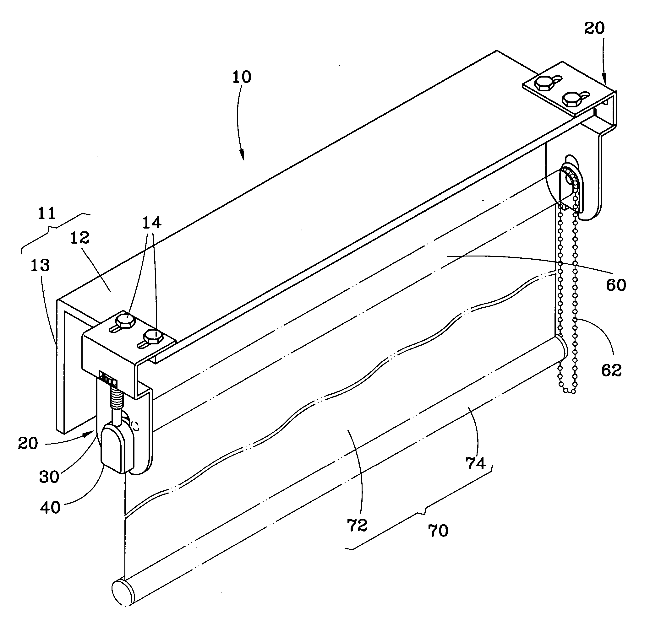
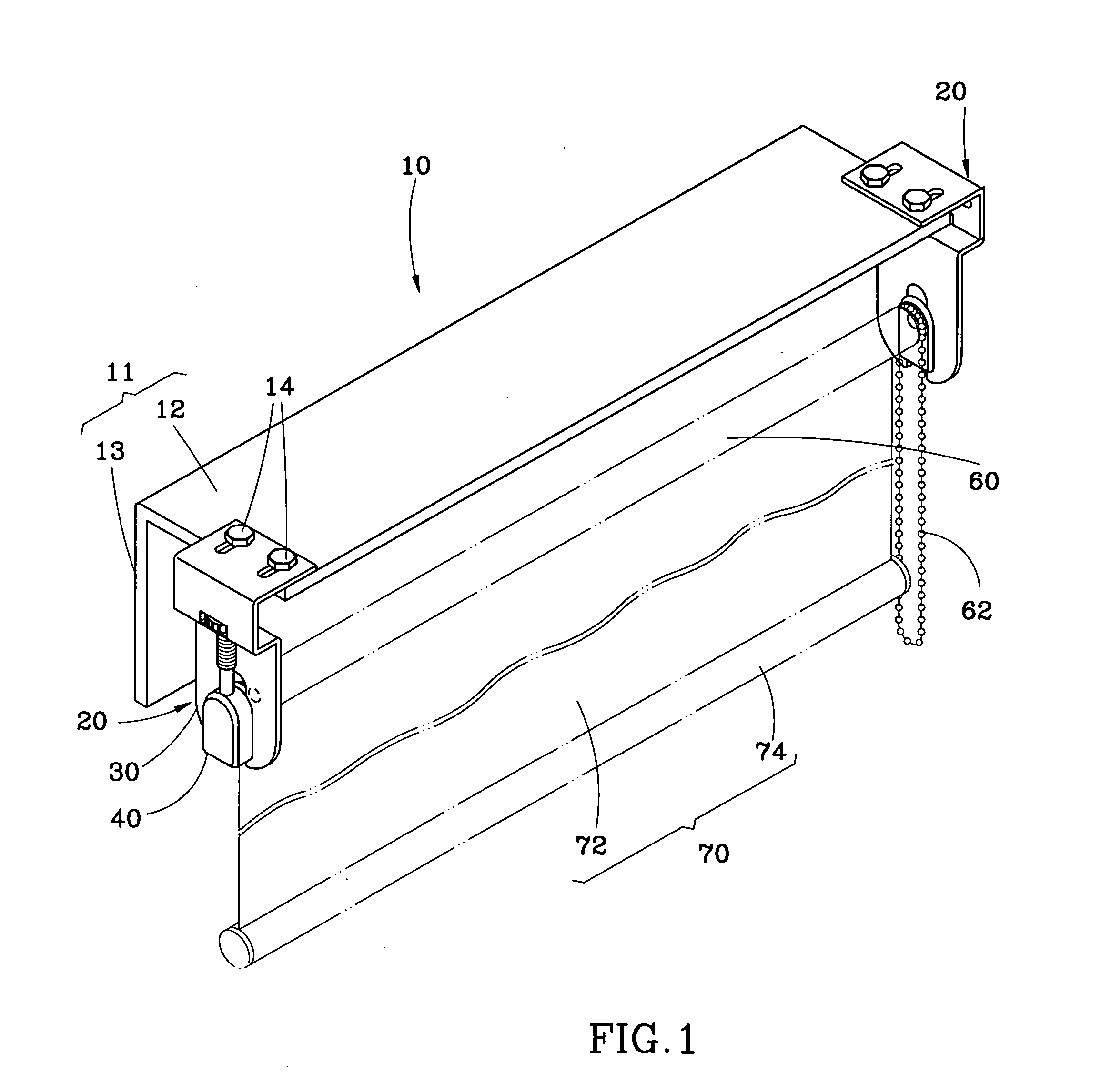
[0014] Referring to FIGS. 1-4, two roller level adjustment devices 20 are shown used in a roller blind 10. The roller blind 10 comprises a bracket 11, a roller 60, and a shade 70. The bracket 11 is shaped like an angle bar, having a top wall 12 transversely (horizontally) provided at the top side of the window, and a side wall 13 perpendicularly downwardly extended from the top wall 12 along the length. The roller 60 is a cylinder transversely (horizontally) pivotally connected between the roller level adjustment devices 20 below the top wall 12 of the bracket 11. An operating cord (chain) 62 is provided at one end of the roller 60 for pulling by the user to rotate the roller 60. The shade 70 comprises a fabric shade body 71 and a weight rod 72. The roller level adjustment devices 20 are provided at the two distal ends of the bracket 11.

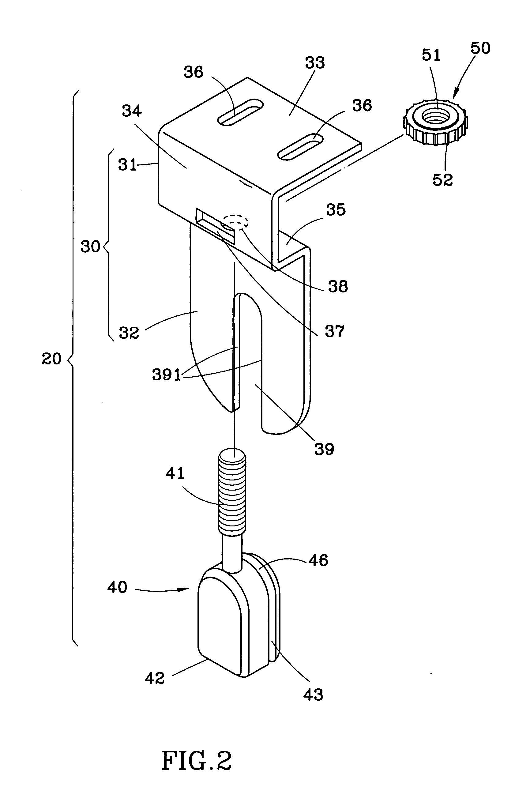
[0015] Each roller level adjustment device 20 comprises a base frame 30, a moveable member 40, and an adjustment member 50. The base frame 30 is ma...


PUM


Abstract

An adjustment device for a roller blind having a bracket and a roller that is pivoted to the bracket and for adjusting the level of the roller includes a base frame, a moveable member and an adjustment member. The base frame is fastened to an end of the bracket. The moveable member, which is moveably mounted on the base frame, has a mounting hole for holding an end of the roller. The adjustment member is mounted in the base frame for moving the moveable member to further move the roller vertically up and down relative to the base frame.

Description

BACKGROUND OF THE INVENTION [0001] 1. Field of the Invention [0002] The present invention relates to a roller blind and more particularly, to an adjustment device for use in a roller blind for enabling the user to adjust the level of the roller of the roller blind. [0003] 2. Description of the Related Art [0004] A regular roller blind generally comprises a bracket, a roller pivotally mounted in the bracket, a shade fastened to the roller, and an operating cord coupled to one end of the roller for pulling by the user to rotate the roller. The bracket is transversely (horizontally) provided at the top side of the window. The shade comprises a fabric shade body, which has a top side fixedly fastened to the periphery of the roller and a bottom side mounted with a weight rod. When operating the operating cord to rotate the roller, the roller is biased to roll up or let off (extend out) the shade body. By means of the gravity weight of the weight rod, the shade body is maintained smoothly...

Claims


Application Information

Patent Timeline
IPC IPC(8): E06B9/50
CPCE06B9/50
Inventor NIEN, MING
Owner NIEN MADE ENTERPRISE CO LTD
Features
  • Generate Ideas
  • Intellectual Property
  • Life Sciences
  • Materials
  • Tech Scout
  • Unparalleled Data Quality
  • Higher Quality Content
  • 60% Fewer Hallucinations
Learn More