

Radio frequency accelerator tube microwave parameter adjusting device
A technology for adjusting devices and microwave parameters, which is applied in the field of radio frequency acceleration tube microwave parameter adjustment devices, can solve the problems of low operation accuracy and poor consistency, and achieve the effects of convenient operation, good consistency, and reasonable structural design
- Summary
- Abstract
- Description
- Claims
- Application Information
AI Technical Summary
Problems solved by technology
Method used
Image


Examples
Embodiment 1
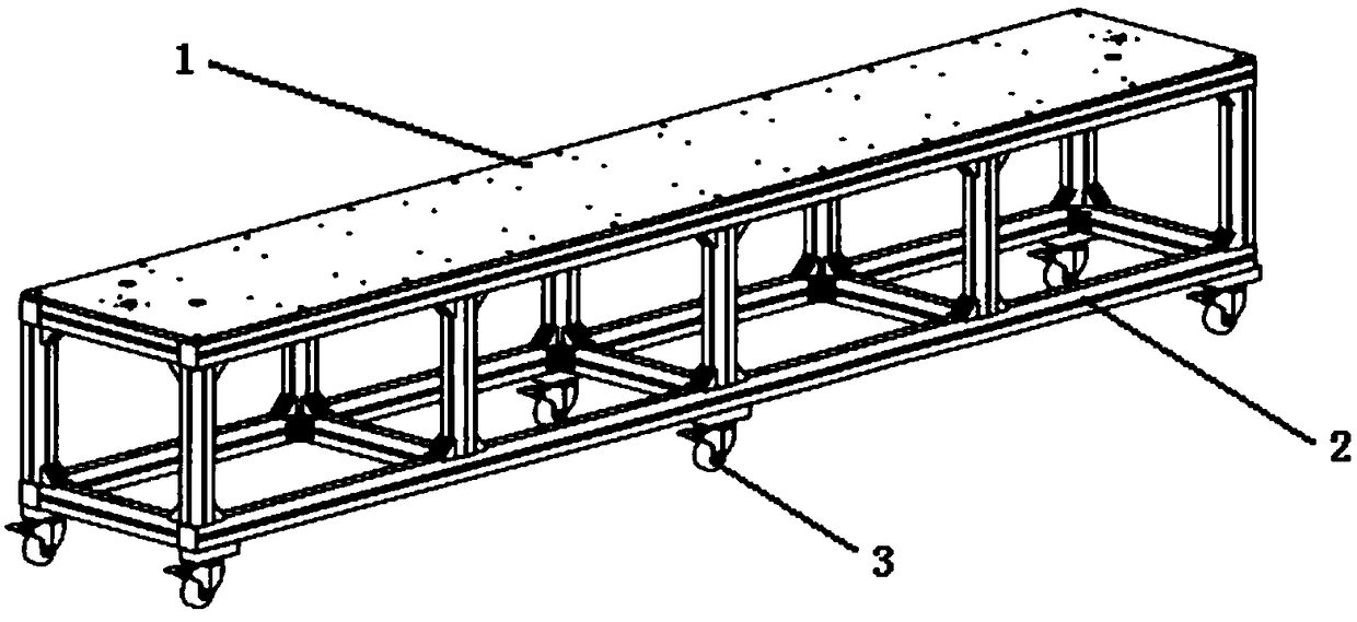
[0030] Adopt the tuning system of the present invention to carry out microwave parameter tuning to a certain radio frequency accelerating tube (referring to appendix Figure 1-3 ), the main steps are as follows:
[0031] (1) Determine the cavity to be tuned and the tuning amount, such as the No. 25 cavity in this embodiment, the tuning amount is ﹢800kHz;
[0032] (2) Slide the tuning device mobile module along the first slide rail 4 to the position of the cavity to be tuned;
[0033] (3) Tuning the cavity through tuning equipment.
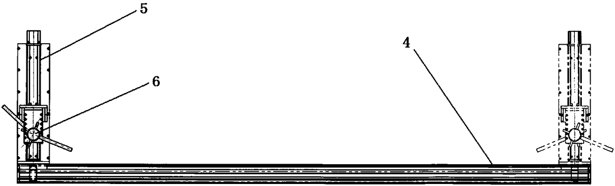
[0034] The tuning equipment of step (3) can also be attached Figure 4 The operation of the tuning process of the tuning device 6 shown is as follows: Screw the tuning screw 7 into the tuning hole of the cavity and tighten it; tune the cavity by turning the tuning knob 8, and stop when the tuning amount reaches +800kHz. Remove the cavity to complete the tuning.
[0035] Practical applications show that the above tuning process is more convenien...
Embodiment 2
[0037] Adopt probe measurement system of the present invention to carry out single cavity (or cavity chain) measurement to certain radio frequency accelerating tube (see attached Figure 5 ), the main steps are as follows:
[0038] (1) Place the cavity to be tested (or the cavity chain) on the V-groove module 14;
[0039] (2) Adjust the horizontal height of the probe, make the first probe moving module 15 and the second probe moving module 16 slide along the second slide rail 13, so that the probe reaches the measurement of the cavity to be measured (or cavity chain) Location;
[0040] (3) record the measured value;
[0041] (4) Remove the first probe moving module 15 and the second probe moving module 16, take off the cavity body (or cavity chain), and complete the measurement.
[0042] The practical application shows that the above-mentioned measurement process is very convenient and quick to operate, the measurement result is high-precision, the adjustment of the probe l...
Embodiment 3
[0044] Adopt the non-resonant perturbation measurement system of the present invention to carry out whole tube measurement to certain radio frequency acceleration tube (see attached Figure 6-7 ), the main steps are as follows:
[0045](1) Pass the measuring line through the radio frequency accelerating tube to be tested;
[0046] (2) adjust the distance between the first pulley 24 and the second pulley 25 respectively, the distance between the third pulley 26 and the fourth pulley 27, make it adapt to the size of the radio frequency acceleration tube to be measured;
[0047] (3) Drive the measurement line through the first pulley 24, so that the perturbation body is moved to 5 cm outside the input end of the acceleration tube;
[0048] (4) Setting the moving speed and moving distance of the perturbation body, measuring the radio frequency accelerating tube to be tested, and obtaining measurement data.
[0049] The practical application shows that the above measurement proce...
PUM
 Abstract
Description
Claims
Application Information