Indexable cutting inserts and methods for producing the same

a cutting edge and indexing technology, applied in the direction of cutting inserts, tool workpiece connection, manufacturing tools, etc., can solve the problems of limiting the useful operating period of that particular cutting edge, superhard material presented to the workpiece, and inherent weak point in the structur

Inactive Publication Date: 2005-08-25
SANDVIK INTELLECTUAL PROPERTY AB
View PDF45 Cites 31 Cited by
  • Summary
  • Abstract
  • Description
  • Claims
  • Application Information

AI Technical Summary

Benefits of technology

[0014] The present invention provides improved indexable c

Problems solved by technology

However, several problems are associated with such techniques.
The braze joint connecting the cutting tips to the body of the cutting insert creates an inherent weak point in the structure.
This is particularly true due to the high temperatures that tend to exist during use of such cutting inserts, these high temperatures being in close proximity to the braze joint.
Another problem posed by such techniques is that the extent of superhard material presented to the workpiece and available for wear is limited, thus limiting the useful operating period for that particular cutting edge.
Such techniques also present certain difficulties.
The process by which the superhard material is bonded to the blank or substrat

Method used


Image

  • Indexable cutting inserts and methods for producing the same
  • Indexable cutting inserts and methods for producing the same
  • Indexable cutting inserts and methods for producing the same

Examples


Embodiment Construction

[0032] Exemplary arrangements and techniques according to the present invention will now be described by reference to the drawing figures.

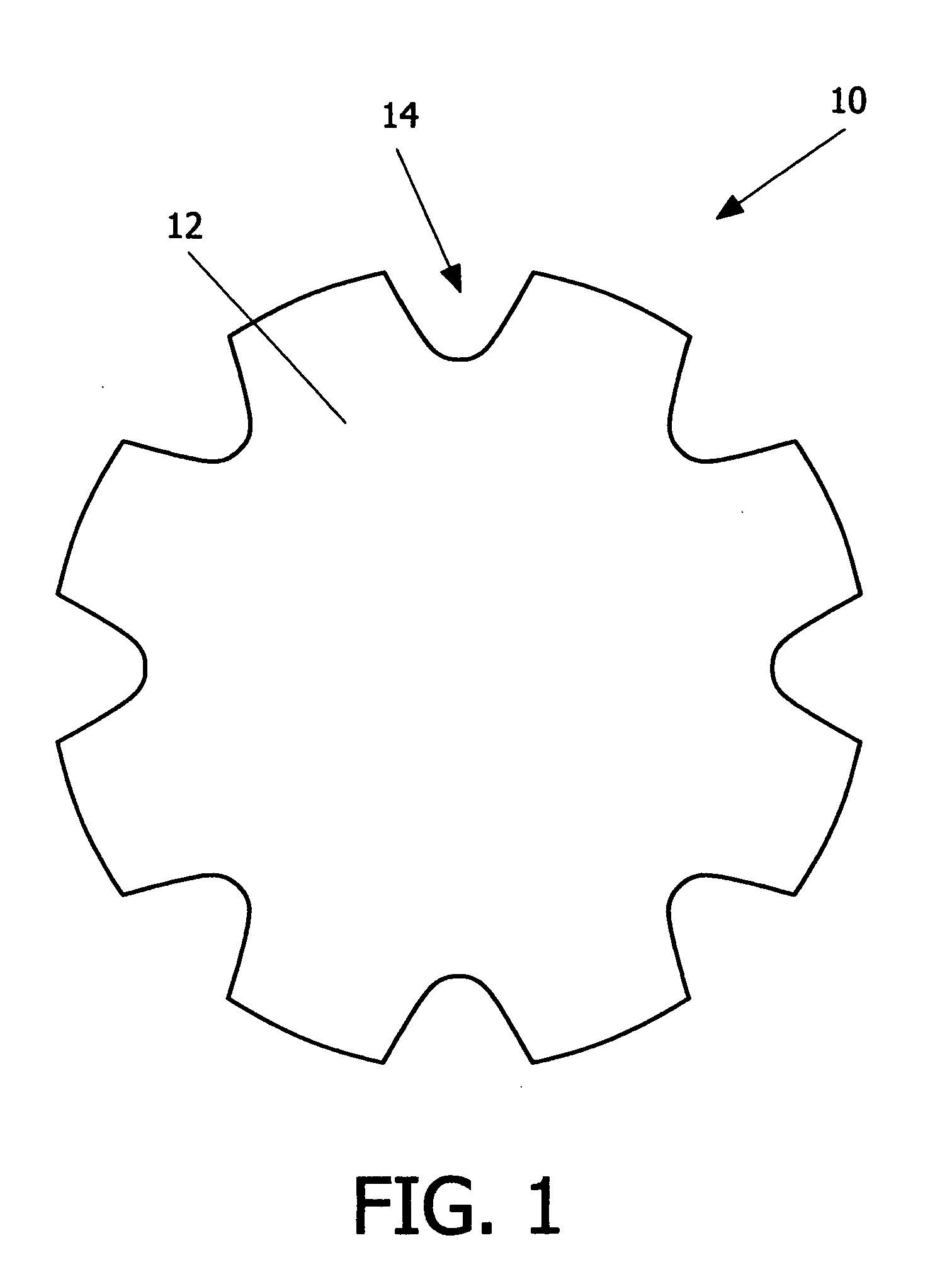
[0033] According to the present invention, a blank is formed from a hard material and a superhard cutting material. The blank having a number of pockets for receiving superhard cutting material and a superhard cutting material therein. An illustrative embodiment of such a blank is shown in FIG. 1. As shown in FIG. 1, the blank 10 comprises a substrate 12 of a hard material having a plurality of pockets 14 formed therein. While the blank 10 is illustrated as having a disk-like shape, other geometries are clearly possible, such as a polygon. It is also possible to form a through-hole in the blank 10, which may facilitate handling. Similarly, the pockets 14 may have a size, location, distribution, and number with differ from the illustrated embodiment. For example, the pockets 14 are shown as having a curved or arcuate shape. However, other shapes a...


PUM

PropertyMeasurementUnit
Lengthaaaaaaaaaa
Percent by massaaaaaaaaaa
Lengthaaaaaaaaaa

Abstract

A method of making a cutting insert includes: (i) forming a blank having a substrate and superhard material, the substrate having more than 4 pockets, the superhard material disposed within the pockets; (ii) removing cutting tips from the blank by cutting the blank along cutting lines; (iii) providing a cutting insert body having a plurality of cavities for receiving a corresponding number of cutting tips; (iv) inserting a cutting tip into each of the plurality of cavities; and (v) brazing the cutting tips to the cutting insert body. A related cutting insert includes: a cutting insert body having a plurality of cavities formed therein; a plurality of cutting tips, each of the plurality of cutting tips disposed in a respective cavity, the cutting tips having a geometry that provides a mechanical retention or lock when inserted into the cavities of the cutting insert body, said geometry including a generally trapezoidal anchor portion with its base substantially flat and spaced away form the cutting edge of the body, the cutting tips further being brazed in the cutting insert body.

Description

CROSS-REFERENCE TO RELATED APPLICATION [0001] This application is a continuation-in-part application of U.S. patent application Ser. No. 10 / 918,391, filed Aug. 16, 2004 (Attorney Docket No. 024445-308).FIELD OF THE INVENTION [0002] The present invention relates to cutting inserts having cutting edges formed from a superhard abrasive material, and methods of making the same. BACKGROUND OF THE INVENTION [0003] In the description of the background of the present invention that follows, reference is made to certain structures and methods, however, such references should not necessarily be construed as an admission that these structures and methods qualify as prior art under the applicable statutory provisions. Applicants reserve the right to demonstrate that any of the referenced subject matter does not constitute prior art with regard to the present invention. [0004] Indexable cutting inserts typically have a polygonal shape with a superhard material disposed generally at the corners. ...

Claims


Application Information

Patent Timeline
IPC IPC(8): B22F7/06B23B27/00B23B27/04B23B27/14B23B51/00B23P15/28E21B10/36E21B10/56E21B10/573
CPCB22F5/003B22F7/06E21B10/573C22C2026/005B23P15/28B23B2240/21B23B2240/11B22F2005/001B22F2998/00B22F2998/10B23B27/007B23B27/04B23B27/141B23B51/00B23B2200/201B23B2215/68B23B2226/125B23B2226/18B23B2226/315B23B2240/08C22C26/00B26D3/00
Inventor SJOGREN, CLAS E.LINDHOLM, MIKAEL
Owner SANDVIK INTELLECTUAL PROPERTY AB
Why Eureka
Try Eureka