Exciter for directly vibrating board

a technology of exciter and direct vibrating, which is applied in the direction of diaphragm construction, electrical transducers, mechanical energy handling, etc., can solve the problems of inability to replace only the exciter, the fastening torque in the turning work cannot be constant, and the speaker of too large nominal size cannot be used, etc., to achieve the effect of sufficient fastening torque, sufficient release torque, and sufficient fastening torque or release torqu

Active Publication Date: 2005-08-25
FUJITSU GENERAL LTD
View PDF10 Cites 25 Cited by
  • Summary
  • Abstract
  • Description
  • Claims
  • Application Information

AI Technical Summary

Benefits of technology

[0014] An object of the present invention is to provide an exciter for directly vibrating a board which enables a sufficient rotational torque to be obtained by a work tool at the time of attachment or detachment.
[0019] As explained above, according to the present invention, it is possible to provide an exciter for directing vibrating a board utilized as a vibration board wherein the coupler member of the exciter is provided with engagement means enabling engagement with an end of a work tool when attaching the coupler member to a bracket member attached to the board or when detaching it from the bracket member, so a sufficient fastening torque can be obtained when mounting the exciter to the board and a sufficient release torque can be obtained when replacing an exciter.
[0021] Further, the engagement means may utilize the plurality of elastic member supports provided at the coupler member forming part of the exciter and form projecting parts at the elastic member supports, so it is possible to make the ends of a work tool engage with the projecting parts and possible to obtain a sufficient fastening torque or release torque.
[0022] By providing these engagement means at the exciter, the turning work is improved when attaching the exciter to the board or when detaching the exciter from the board.

Problems solved by technology

Speakers of too large nominal sizes cannot be used.
If however the coupler member is fixed to the board, when for example the exciter is damaged and the speaker no longer function, it is not possible to replace only the exciter.
However, if workers manually turn exciters when attaching them, the fastening torques in the turning work cannot be made constant and sometimes sufficient fastening torques cannot be applied.
The insufficient fastening at the time of attachment of the exciter causes loose attachment and degrades the performances of the speaker.
Further, the exciters may even drop off.
The ends of the work tools end up slipping at the outer circumference, so sufficient fastening torques cannot be obtained.
On the other hand, if too strongly fastening the exciter—not only when attaching it, but also when detaching it for replacement, the ends of the work tools end up slipping at the outer circumference of the outside yoke and therefore the exciter cannot be turned.

Method used


Image

  • Exciter for directly vibrating board
  • Exciter for directly vibrating board
  • Exciter for directly vibrating board

Examples


first embodiment

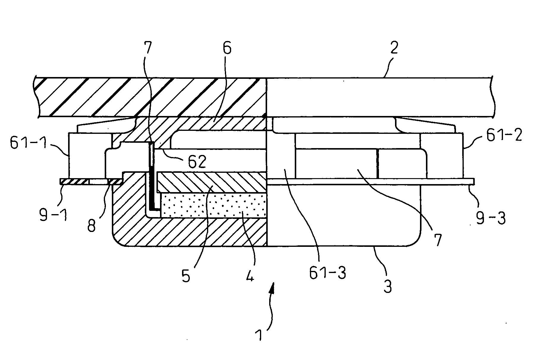
[0044] The exciter for directly vibrating a board according to the first embodiment is similar to the exciter 1 shown in FIG. 5 and FIG. 6. In the first embodiment, engagement means gripped by engagement with a work tool when mounting or detaching the exciter 1 are formed at the outer circumference of the side wall of the outside yoke 3 of the exciter 1. The engagement means comprise flat surfaces formed by grinding down parts of the outer circumference of the side wall.

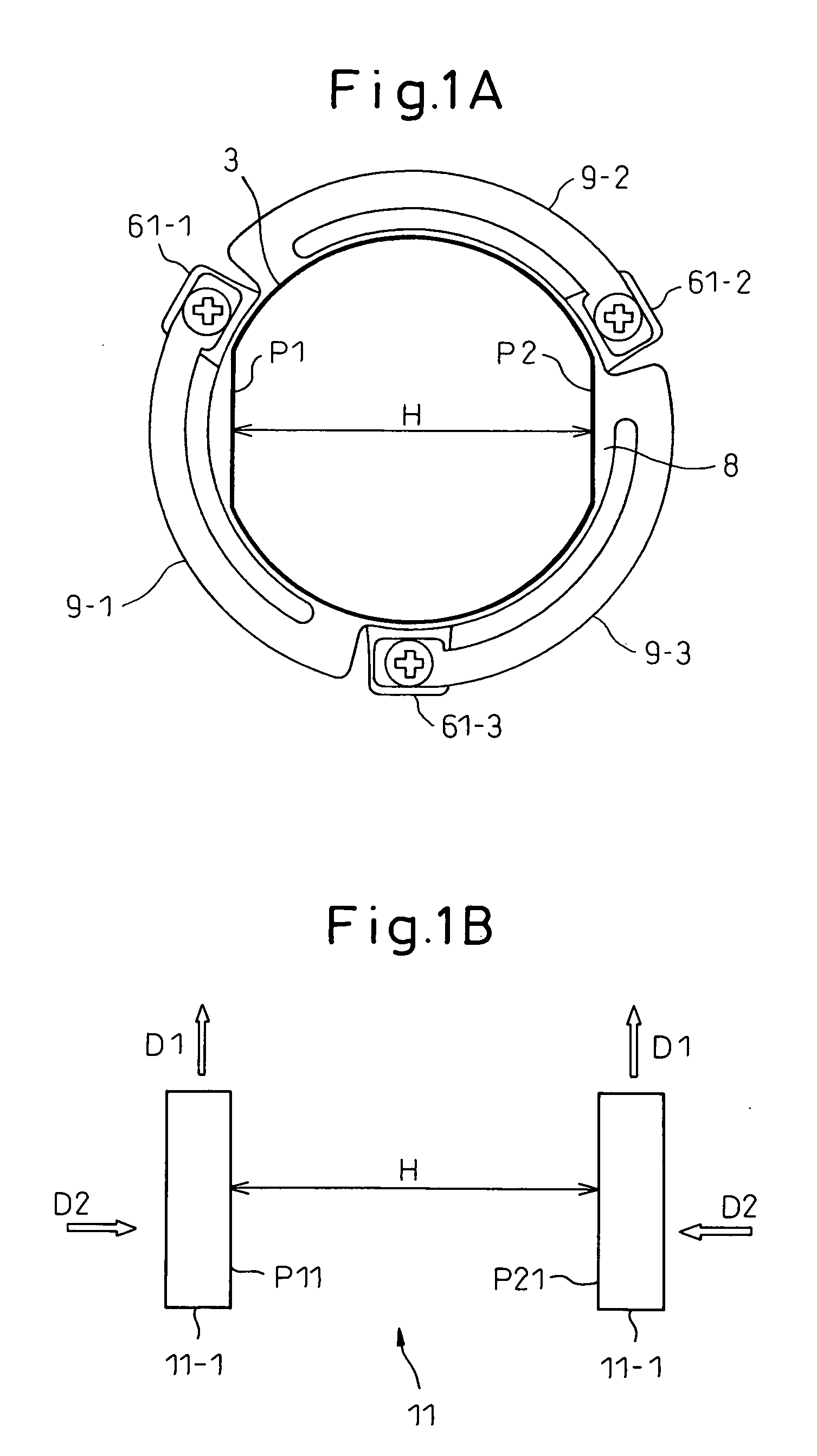
[0045] The state of formation of the engagement means at the outer circumference of the side wall of the outside yoke 3 of the exciter 1 is shown in FIG. 1A. The figure shows the state as seen from the bottom of the outside yoke 3 of the exciter 1. This is similar to the exciter 1 shown in FIG. 6. The same parts are assigned the same reference number. In FIG. 1A, the outside yoke 3 is shown by the bold line. As engagement means, two parallel facing flat surfaces P1 and P2 are formed.

[0046] On the other hand, FIG. 1...

second embodiment

[0056] The engagement means in the exciter for directly vibrating a board according to the second embodiment are shown in FIG. 3A. In the first embodiment, the engagement means with which the ends of the work tool engaged were formed at the outer circumference of the outside yoke of the exciter. As opposed to this, in the second embodiment, the engagement means are formed at the bottom of the outside yoke of the exciter. The engagement means in this case basically comprises a narrow groove with which the end of a work tool can engage.

[0057] The exciter for directly vibrating a board shown in FIG. 3A is similar in configuration to the exciter for directly vibrating a board shown in FIG. 6. The same parts are assigned the same notations. The engagement means of the exciter of FIG. 3A comprise a single long groove S1 at the bottom of the outside yoke 3 of the exciter 1. The length of the groove S1 is selected so that a sufficient torque is obtained when the end of a work tool 11 is en...

third embodiment

[0060] The engagement means in an exciter for directly vibrating a board according to a third embodiment are shown in FIG. 4. In the first embodiment and second embodiment, the engagement means with which the ends of the work tools engaged were formed at the outer circumference or bottom of the outside yoke of the exciter. As opposed to this, in the third embodiment, the engagement means are formed not at the outside yoke of the exciter, but at the coupler member provided with elastic member supports for supporting the vibratable elastic members of the magnetic circuit unit.

[0061] The exciter for directly vibrating a board shown in FIG. 4 is similar in configuration to the exciter for directly vibrating a board shown in FIG. 6. The same parts are assigned the same reference numbers. Note that in FIG. 4, a quarter of the exciter shown in FIG. 6 is shown enlarged. The engagement means of the exciter of FIG. 4 utilize the elastic member supports 61-1 to 61-3 supporting the elastic mem...


PUM


Abstract

An exciter for directly vibrating a board, which enables a sufficient rotational torque to be obtained by a work tool at the time of attachment or detachment, provided with a magnetic circuit unit having an outside yoke comprised of a side wall and a bottom, a permanent magnet fastened to the bottom, and an inside yoke and with a coil inserted into a clearance between the side wall and inside yoke, the magnetic circuit unit being vibratably supported at the coupler member by elastic members, the coupler member being screwed with the bracket member fastened to the surface of the board, two parallel flat surfaces engaging with ends of a work tool being provided at an outer circumference of the outside yoke, and the work tool being turned to attach / detach the coupler member with respect to the bracket member.

Description

CROSS-REFERENCE TO RELATED APPLICATION [0001] This application claims the priority of Japanese Patent Application No. 2004-44819, filed on Feb. 20, 2004. BACKGROUND OF THE INVENTION [0002] 1. Field of the Invention [0003] The present invention relates to an exciter directly attached to a board for vibrating the board. In particular, the present invention relates to an exciter for directly vibrating a board which is designed so that when attached to a board via a bracket member, it will not be insufficiently fastened to the bracket member. [0004] 2. Description of the Related Art [0005] In the past, in stereo systems, PCs, mobile phones, and other electronic apparatuses, speakers have been used to output audio information from various media. In such speakers, vibration boards for emitting sound are attached to exciters supplied with the drive signals for audio output. These vibration boards have horn shapes specially designed for such speakers. For example, the vibration boards have ...

Claims


Application Information

Patent Timeline
Patent Type & Authority Applications(United States)
IPC IPC(8): H02K9/00H02K33/00H04R1/00H04R9/04H04R7/04H04R9/02H04R9/06
CPCH04R9/06H04R9/066
Inventor NAKAJIMA, YUICHIOHTANI, KIYOSHINISHIKAWA, AKIRAHIDAKA, NOBORU
Owner FUJITSU GENERAL LTD
Why Eureka
Try Eureka