Pierce nut for high-strength steel plate

a technology of steel plate and nut, which is applied in the direction of threaded fasteners, mechanical devices, fastening means, etc., can solve the problems of reducing the strength of the pierce nut against separation from the steel plate s, insufficient peeling strength after attachment, and insufficient rotation torque of the pierce nut, so as to ensure the peeling strength in the axial direction, increase rigidity, and ensure the effect of rotation torqu

Active Publication Date: 2016-05-03
AOYAMA SEISAKUSHO CO LTD
View PDF8 Cites 0 Cited by
  • Summary
  • Abstract
  • Description
  • Claims
  • Application Information

AI Technical Summary

Benefits of technology

[0014]In a pierce nut for a high-strength steel plate according to the invention, the outer peripheral surface of a piercing portion forms a first sloping surface, and also the inner peripheral surface of an outer peripheral projection forms a second sloping surface increasing in diameter toward the leading end thereof, and an annular groove is formed between these sloping surfaces. In contrast to a conventional pierce nut in which the inner peripheral surface of an outer peripheral projection forms a sloping surface decreasing in diameter toward the leading end thereof, the pierce nut according the invention is configured such that the corresponding inner peripheral surface forms a sloping surface increasing in diameter toward the leading end thereof. Accordingly, even where a mating member is a high-strength steel plate, the peripheral edge portions of the hole in the steel plate, made by the piercing portion as a result of having run through it, easily flow into the annular groove. The inner peripheral edge portion of the steel plate, which has flowed into the annular groove, comes into secure contact with the outer periphery of the piercing portion, and thus peeling strength in the axial direction can be ensured.
[0015]Additionally, the outer peripheral edge portion of the steel plate, which has flowed into the annular groove, comes into secure contact with the inner periphery of the outer peripheral projection. However, since this inner periphery has serrations, sufficient rotation torque can be ensured. Moreover, the outer peripheral projection has a trapezoidal sectional shape in which the dimension on the nut body side is wide, thus increasing rigidity and preventing conventional deformation.

Problems solved by technology

Therefore, a conventional pierce nut has a problem in that its peeling strength after attachment insufficient.
However, in FIG. 1(B), since the hardness of the steel plate S is high, the steel plate S cannot sufficiently flow into the annular groove 3.
Consequently, the strength of the pierce nut against separation from the steel plate S decreases, and also contact of the steel plate S with the outer peripheral projection 2 is insufficient, resulting in insufficient rotation torque.
However, complete elimination of the outer peripheral projection 2 may lead to a decrease in peeling strength of the pierce nut from the steel plate.

Method used


Image

  • Pierce nut for high-strength steel plate
  • Pierce nut for high-strength steel plate
  • Pierce nut for high-strength steel plate

Examples


Embodiment Construction

[0021]An embodiment according to the invention will be described below. A pierce nut for a high-strength steel plate according to the invention can also be used for a high-strength steel plate for which a conventional pierce nut cannot be used. A pierce nut according to the invention can also be used for a conventional low-strength steel plate.

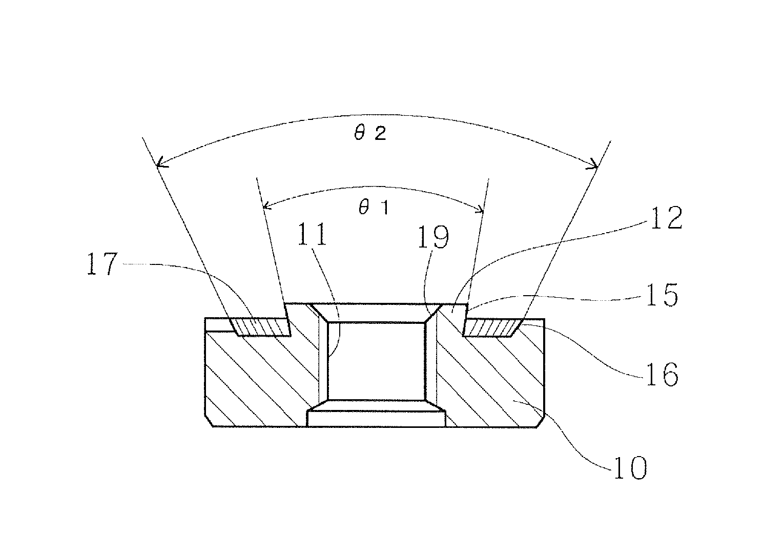
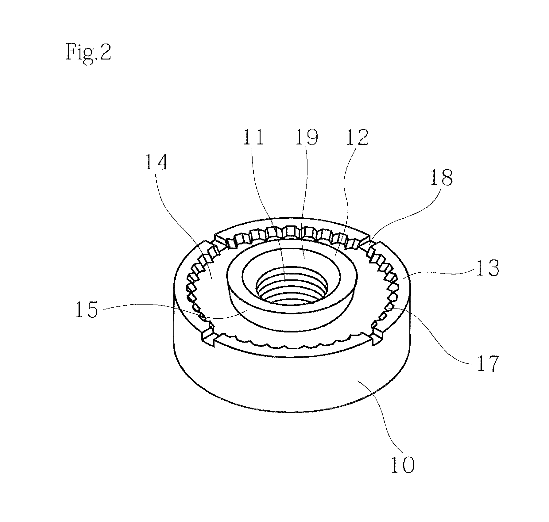
[0022]FIGS. 2 to 4 show a pierce nut for a high-strength steel plate. The reference 10 represents a nut body in a short cylindrical form; 11, a female screw thread portion formed in the center of the nut body; 12, an annular piercing portion formed on the outer periphery of the female screw thread portion 11; 13, an annular outer peripheral projection extending from the outer periphery of the nut body 10; 14, an annular groove formed between the piercing portion 12 and outer peripheral projection 13. As shown in FIG. 3, the height of the projection of the piercing portion 12 is greater than that of the outer peripheral projection 13. The nut b...


PUM


Abstract

A pierce nut used for a high-strength steel plate according to the invention includes a female screw thread portion formed in the center of a nut body, an annular piercing portion projecting around the female thread portion, and an annular outer peripheral projection extending from the periphery of the nut body. The outer periphery of the piercing portion forms a first sloping surface increasing in diameter toward the leading end thereof, and also the inner peripheral surface of the outer peripheral projection forms a second sloping surface increasing in diameter toward the leading end thereof. Serrations are formed on the second sloping surface. Even where a mating member is a high-strength steel plate, the pierce nut according to the invention can ensure the same peeling strength and rotation torque as with a conventional nut, without deformation of the pierce nut itself.

Description

TECHNICAL FIELD[0001]The present invention relates to a pierce nut used for a high-strength steel plate.BACKGROUND ART[0002]Conventionally, many pierce nuts are used in vehicles, typically automobiles. In general, a pierce nut includes a female screw thread portion formed in the center of a nut body, an annular piercing portion projecting around the female screw thread portion, and an annular outer peripheral projection extending from the periphery of the nut body.[0003]Therefore, by driving the pierce nut into a steel plate, which is a mating member of the nut, the piercing portion runs through the mating member to make a circular hole therein, and at the same time, plastically deforms the steel plate around the peripheral edge portion of the hole by virtue of plasticity such that the steel plate flows into an annular groove formed between the piercing portion and the outer peripheral projection. Consequently, the pierce nut is securely fixed to the mating member. Thus, the pierce ...

Claims


Application Information

Patent Timeline
Patent Type & Authority Patents(United States)
IPC IPC(8): F16B37/04F16B37/06F16B37/00
CPCF16B37/00F16B37/068
Inventor TANAKA, MAMORUIKAMI, HIDENORI
Owner AOYAMA SEISAKUSHO CO LTD
Why Eureka
Try Eureka