Electric tool

a technology of electric tools and electric motors, applied in the field of impact-type electric tools, can solve the problems of increasing counter-torque applied to impact tools, increasing disengaging torque, and difficulty for operators to hold impact tools in one hand to fasten screws, so as to suppress the increase of disengaging torque of hammers and enhance striking force. , the effect of preventing cambered

Inactive Publication Date: 2017-02-09
HITACHI KOKI CO LTD
View PDF19 Cites 16 Cited by
  • Summary
  • Abstract
  • Description
  • Claims
  • Application Information

AI Technical Summary

Benefits of technology

[0008]The timing of transition from continuous rotation to the striking operation is delayed when the disengaging torque increases. Thus, the counter torque applied on the impact tool increases and makes it difficult for the operator to hold the impact tool in one hand to fasten screws. Moreover, in the case of fastening screws into soft wood or the like that does not require a high fastening torque, the impact tool with the increased spring constant may not reach the disengaging torque in the screw fastening operation, which results in the problem that the striking operation is hard to carry out. If the striking operation could not be performed, the screw threads of the tip tool may easily float from the cross groove of the drywall screw and the hexagonal bit may come off and be repelled. In that case, the tip tool rotates idly and damages the screw head of the drywall screw. In this way, the impact tool does not perform its characteristics when the disengaging torque is too high and particularly the effect of preventing cam-out is not achieved.
[0009]In view of the above background, the invention provides an impact type electric tool that suppresses increase of the disengaging torque of the hammer and the anvil and enhances the striking force in the rotational direction to achieve high output power as well as allows the operator to carry out the screw fastening operation by holding the electric tool in one hand.
[0010]The invention also provides an electric tool that achieves high output power as well as improves the operation feeling during transition from continuous rotation to striking. The invention further provides an electric tool, in which the hammer striking claw strikes the struck claw following the next struck claw of the anvil to ensure a sufficient fastening torque without increasing the spring constant of the hammer spring.

Problems solved by technology

However, the inventors found that, if the spring constant of the spring is increased to achieve high output power, the disengaging torque also increases and the following problems occur.
Thus, the counter torque applied on the impact tool increases and makes it difficult for the operator to hold the impact tool in one hand to fasten screws.
Moreover, in the case of fastening screws into soft wood or the like that does not require a high fastening torque, the impact tool with the increased spring constant may not reach the disengaging torque in the screw fastening operation, which results in the problem that the striking operation is hard to carry out.
If the striking operation could not be performed, the screw threads of the tip tool may easily float from the cross groove of the drywall screw and the hexagonal bit may come off and be repelled.
In that case, the tip tool rotates idly and damages the screw head of the drywall screw.
In this way, the impact tool does not perform its characteristics when the disengaging torque is too high and particularly the effect of preventing cam-out is not achieved.

Method used


Image

  • Electric tool
  • Electric tool
  • Electric tool

Examples


embodiment 1

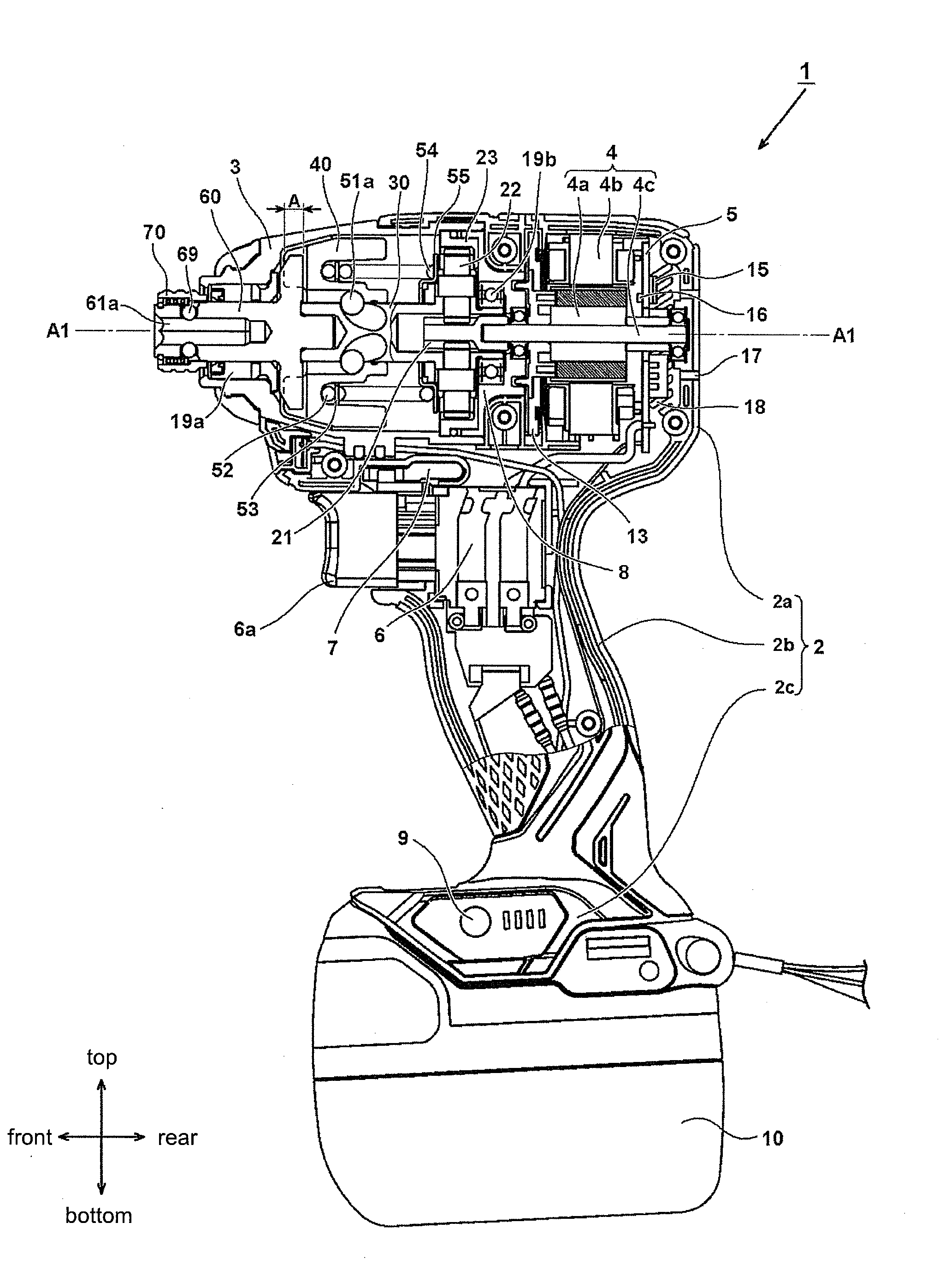
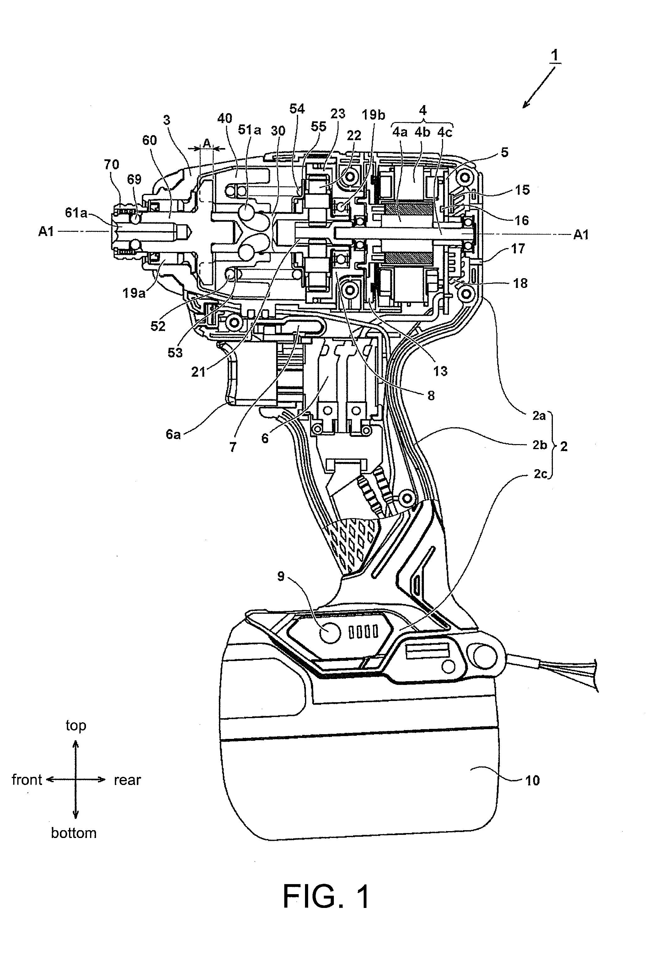
[0038]Hereinafter, embodiments of the invention are described with reference to the figures. In the following description, the vertical direction and the front-rear direction refer to the directions shown in the figures. This embodiment illustrates an impact tool as an embodiment of the electric tool.

[0039]FIG. 1 is a longitudinal cross-sectional view showing the internal structure of an impact tool 1 according to an embodiment of the invention. A housing of the impact tool 1 includes a body housing 2 and a hammer case 3 disposed therein. The impact tool 1 uses a rechargeable battery 10 as a power source and a motor 4 as a driving source to drive a rotational striking mechanism. A rotational force and a striking force from the striking mechanism are applied to an anvil 60 that serves as an output shaft, and the rotational striking force is continuously or intermittently transmitted to a tip tool (not shown), such as a driver bit, held in a mounting hole 61a formed on a bit holding p...

embodiment 2

[0068]Next, the second embodiment of the invention is described with reference to FIG. 12 to FIG. 22. The hammer 40 described in the first embodiment includes three striking claws. However, the method of carrying out the “one-skip striking” as described in the first embodiment is also applicable to the structure of the conventional impact tool, in which the anvil has two blade parts and the hammer has two striking claws, and the striking claws and the blade parts are respectively at positions separated by an angle of 180 degrees. FIG. 12 is a longitudinal cross-sectional view showing the internal structure of an impact tool 101 according to the second embodiment of the invention. The impact tool 101 has the same basic structure as the impact tool 1 of FIG. 1, except that the number of the claws of the hammer and the number of the blade parts of the anvil are both two.

[0069]The impact tool 101 uses a battery 110 as a power source and a brushless type motor 104 as a driving source to ...


PUM


Abstract

Provided is an impact type electric tool. A striking mechanism is used, which uses a hammer having striking claws that are equally arranged in the rotational direction and an anvil having struck claws. A relationship between a striking energy E, which the hammer has right before striking the anvil, and a disengaging torque TB, which is applied between the hammer and the anvil right before the hammer is disengaged from the anvil, is set as 5.3×TB<E<9.3×TB in the case of three claws and set as 9.3×TB<E<15.0×TB in the case of two claws, so as to perform striking by skipping one of the claws of the hammer and the anvil when a high torque is required. Accordingly, the electric tool achieves output of a high torque while maintaining a favorable operational feeling during striking.

Description

CROSS-REFERENCE TO RELATED APPLICATION[0001]This application claims the priority benefits of Japan application serial no. 2015-157817, filed on Aug. 7, 2015, and Japan application serial no. 2016-070906, filed on Mar. 31, 2016. The entirety of each of the above-mentioned patent applications is hereby incorporated by reference herein and made a part of this specification.BACKGROUND OF THE INVENTIONField of the Invention[0002]The invention relates to an impact type electric tool, in which a hammer is capable of applying a striking force to an anvil in a rotational direction.Description of Related Art[0003]Conventionally, an electric tool is known as a device for transmitting a rotational force of a motor to a hammer so as to apply a striking force in the rotational direction to an anvil through the hammer. The impact tool disclosed in Japanese Patent Publication No. S59-88264 is one example. The impact tool is widely used for works such as fastening screw members into lumber or fixing...

Claims


Application Information

Patent Timeline
Patent Type & Authority Applications(United States)
IPC IPC(8): B25B21/02
CPCB25B21/026B25F5/006
Inventor MURAKAMI, TAKUHIROTOKAIRIN, JUNICHITAKEUCHI, SHOTAMASHIKO, HIRONORINOGUCHI, YUTAMATSUSHITA, AKIRA
Owner HITACHI KOKI CO LTD
Why Eureka
Try Eureka