
Data transmission equipment

a technology for transmission equipment and data, applied in the direction of power supply for data processing, instruments, measurement devices, etc., can solve the problems of reducing freedom of placement, affecting the reliability of peripheral devices, so as to achieve reliable recognition of peripheral devices

Inactive Publication Date: 2005-08-25
CONTEC CO LTD
View PDF11 Cites 9 Cited by
  • Summary
  • Abstract
  • Description
  • Claims
  • Application Information

AI Technical Summary

Benefits of technology

[0009] It is an object of the present invention is to provide a data transmission equipment that allows a power supply of a peripheral device to be turned ON / OFF in tandem with ON / OFF of a power supply of a main device without laying a dedicated line, and that permits reliable recognition of the peripheral device by the main device.

Problems solved by technology

However, because parallel cables are used, the cable length is limited to about one meter.
This has therefore posed a problem that the main device and peripheral device must be installed within one meter of one another and the freedom of placement is reduced.
However, when the freedom of placement is raised in this way, ‘power interlocking’ conversely becomes complicated.
That is, due to the small number of lines the serial cables afford, one of these cables cannot be used as a line dedicated to power (a line that transmits a signal to confirm establishment of the power of the main device), and hence it is difficult to turn on the power supply simultaneously.
However, when a dedicated line is laid separately, a problem of increased costs arises.
Accordingly, when OS startup is completed early, a situation arises where the OS is unable to recognize each substrate of the peripheral device.

Method used


Image

  • Data transmission equipment
  • Data transmission equipment
  • Data transmission equipment

Examples


Embodiment Construction

[0016] An embodiment of the present invention will be described hereinbelow with reference to the drawings.

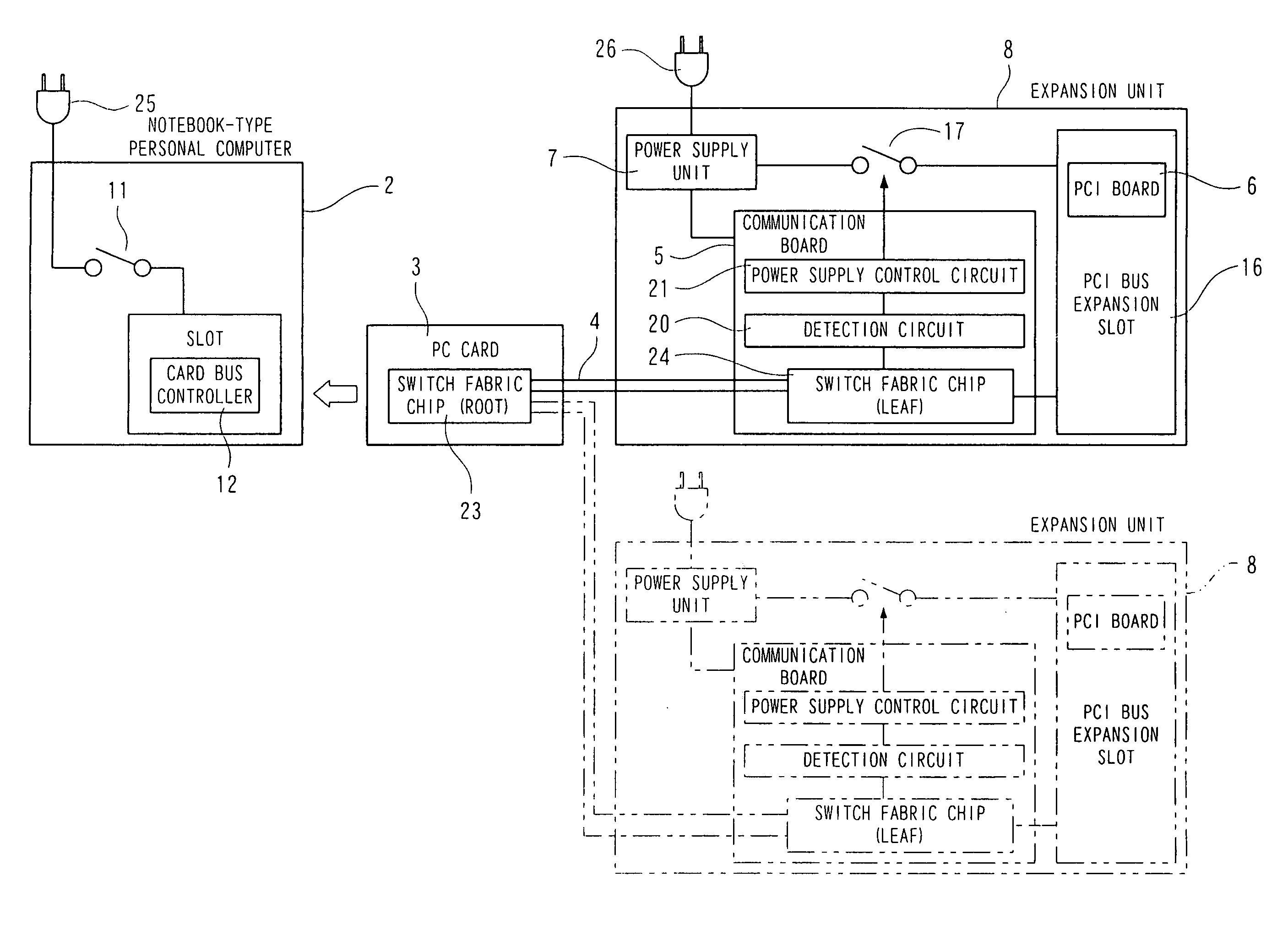
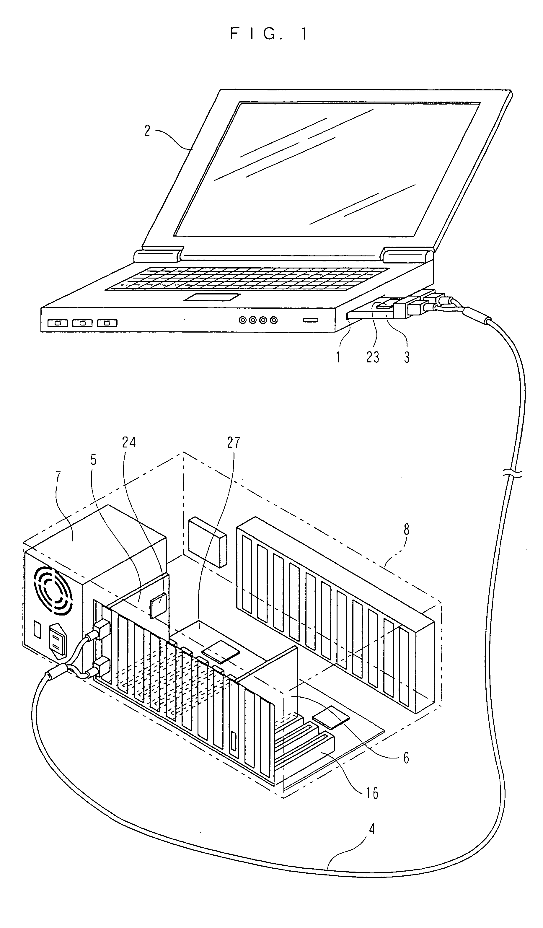
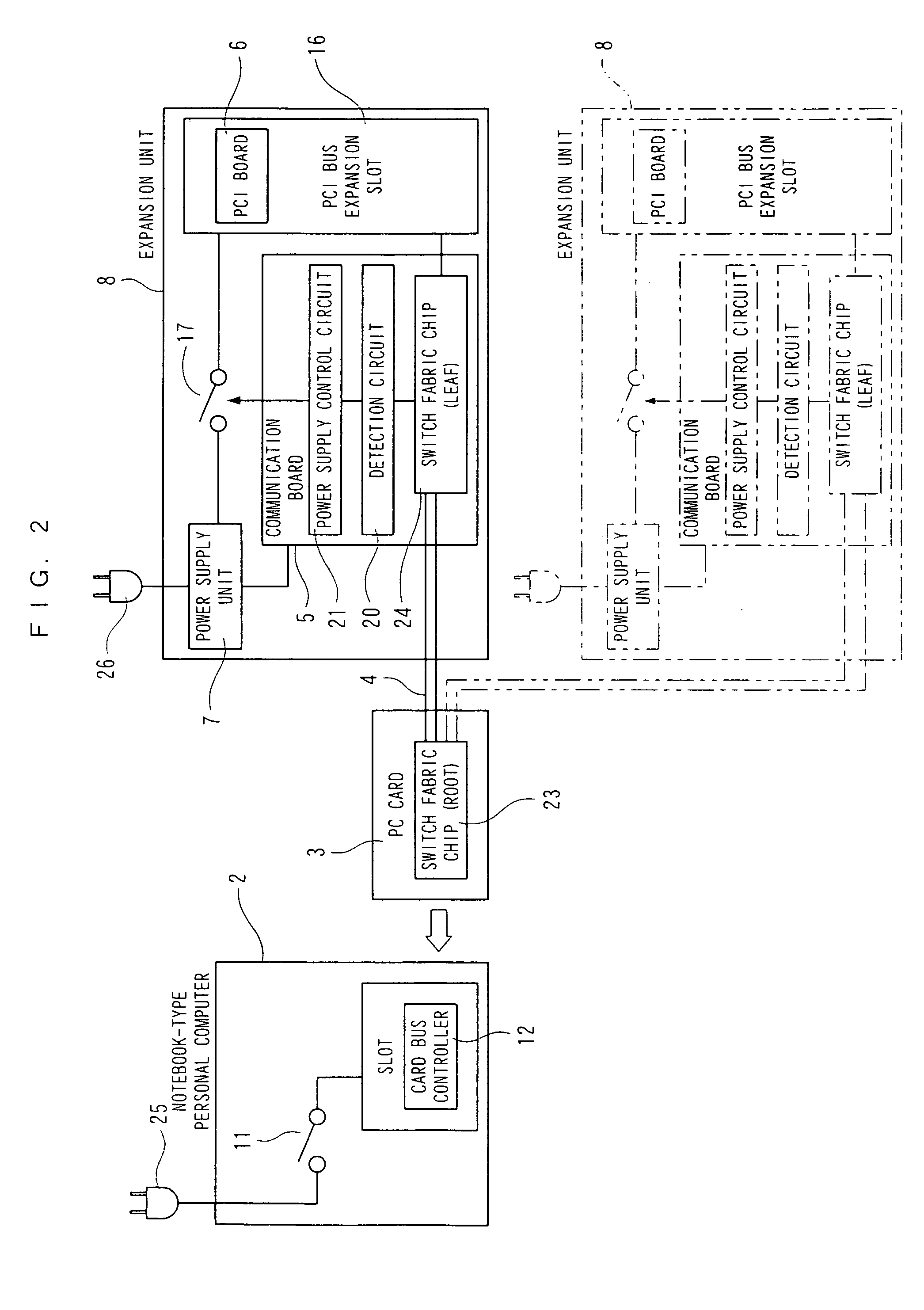
[0017]FIG. 1 is a schematic external view of the data transmission equipment of an embodiment of the present invention and FIG. 2 is a constitutional view of the same data transmission equipment.

[0018] As shown in FIGS. 1 and 2, the data transmission equipment of the present embodiment performs data transmission between a main device (notebook-type personal computer) 2 comprising a computer and having a card slot 1, and an expansion unit (an example of a peripheral device) 8. The main device will be described as a notebook-type personal computer 2 hereinbelow. Further, as indicated by the virtual lines in FIG. 2, a plurality (two in FIG. 2) of the expansion unit 8 can be connected to the notebook-type personal computer 2.

[0019] The notebook-type personal computer 2 is equipped with manipulation devices such as a liquid-crystal screen, keyboard, and so forth as shown in FIG. ...


PUM


Abstract

An expansion unit (peripheral device) includes a detection circuit for detecting establishment of communication between a PC card of a notebook-type personal computer and a communication board of the expansion unit, and a power supply control circuit for powering on the expansion unit in accordance with the detection of the establishment of communication by the detection circuit. The notebook-type personal computer starts up the OS as a result of being powered ON, performs recognition of the PC card in a card slot, supplies power to the PC card and, after a fixed wait time, performs recognition of a PCI board of the expansion unit via the PC card, the serial cable (communication line) and the communication board.

Description

BACKGROUND OF THE INVENTION [0001] 1. Field of the Invention [0002] The present invention relates to data transmission equipment and, more particularly, to power interlocking between a main device which comprises a computer, and a peripheral device. [0003] 2. Description of the Related Art [0004] Data transmission equipment is an equipment that performs data transmission (sends and receives data) between a main device (a computer) and a peripheral device that is connected to the main device. Such data transmission equipment includes an equipment that performs ‘power interlocking’ that turns a power supply of the peripheral device ON / OFF in tandem with the ON / OFF of the power supply of the main device. This equipment is constituted such that the main device and peripheral device are connected by means of parallel cables and, when the power supply of the main device is turned ON, a signal is transmitted by using one of a multiplicity of parallel cables such that the power supply of th...

Claims


Application Information

Patent Timeline
Patent Type & Authority Applications(United States)
IPC IPC(8): G06F15/16G06F1/26
CPCG06F1/266
Inventor TERAMURA, MITSUOKOUNO, ICHIROUNO, MITSUYOSHI
Owner CONTEC CO LTD
Learn More