Rubber polyurethane line

a polyurethane line and rubber technology, applied in the field of liners, can solve the problems of limited functional life of steel pipes, persistent challenges for rubber liners, and expensive and problematic procedures

Inactive Publication Date: 2005-09-01
IRATHANE SYST
View PDF34 Cites 19 Cited by
  • Summary
  • Abstract
  • Description
  • Claims
  • Application Information

AI Technical Summary

Problems solved by technology

Plain steel pipes were once commonly used for this purpose, but breakdown due to abrasion from the slurry material severely limited the functional lifetime of such a steel pipe.
However, rubber liners continue to involve persistent challenges, including expensive and problematic procedures to apply a rubber liner to a steel pipe, and significant deterioration over time of the rubber liner due to exposure to heat, hydrocarbons, and particulate matter.
However, polyurethane liners also had significant performance drawbacks, including significant deterioration over time due to high levels of heat, and permeability to slurry transport fluid which often leads to blistering and disbondment of the liner from the pipe, a failure mode known as “cold wall effect”.
While no ideal pipeline liner solution has been available, the applications for liners have become ever more demanding, owing to the constant effort to develop new and often more challenging options in materials and energy resource extraction.
However, extraction of energy resources from tar sands imposes harsh demands on equipment.
However, under such extreme conditions, these liners quickly break down due to hydrocarbons, heat, abrasion by the particulate matter, and cold wall effect.
CCO liners are extremely expensive and still have only marginal resistance to abrasion by the particulate matter.

Method used


Image

  • Rubber polyurethane line
  • Rubber polyurethane line
  • Rubber polyurethane line

Examples


Embodiment Construction

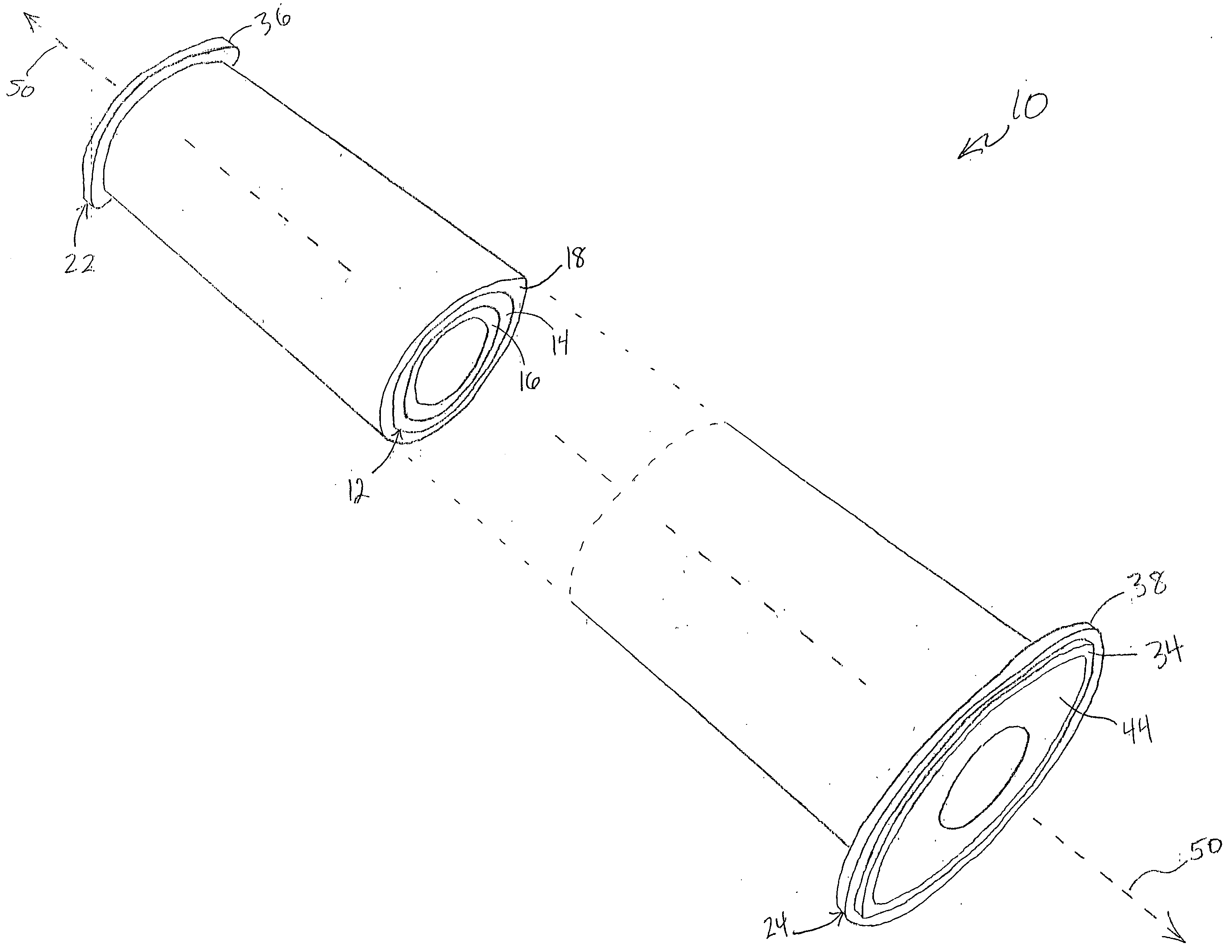
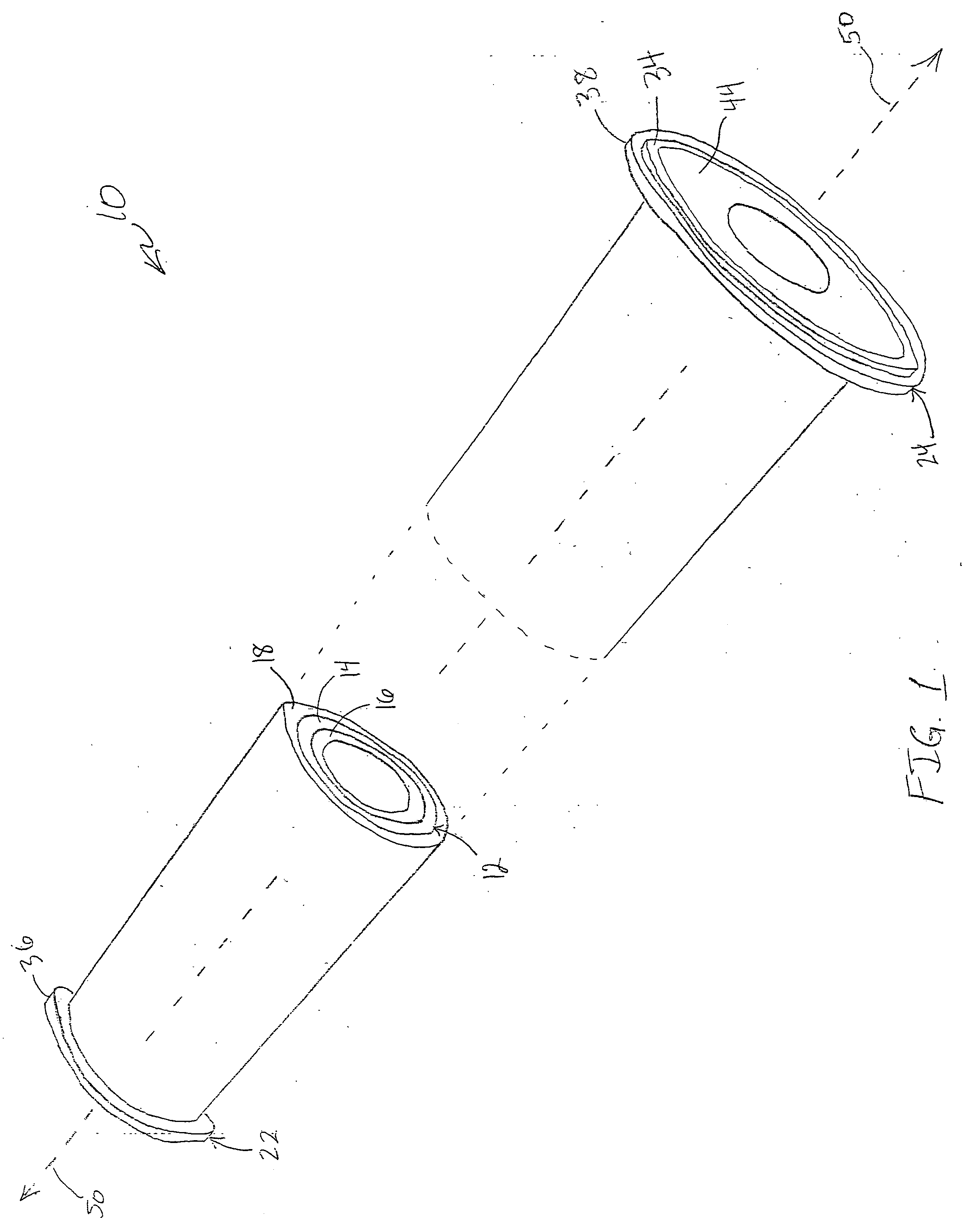
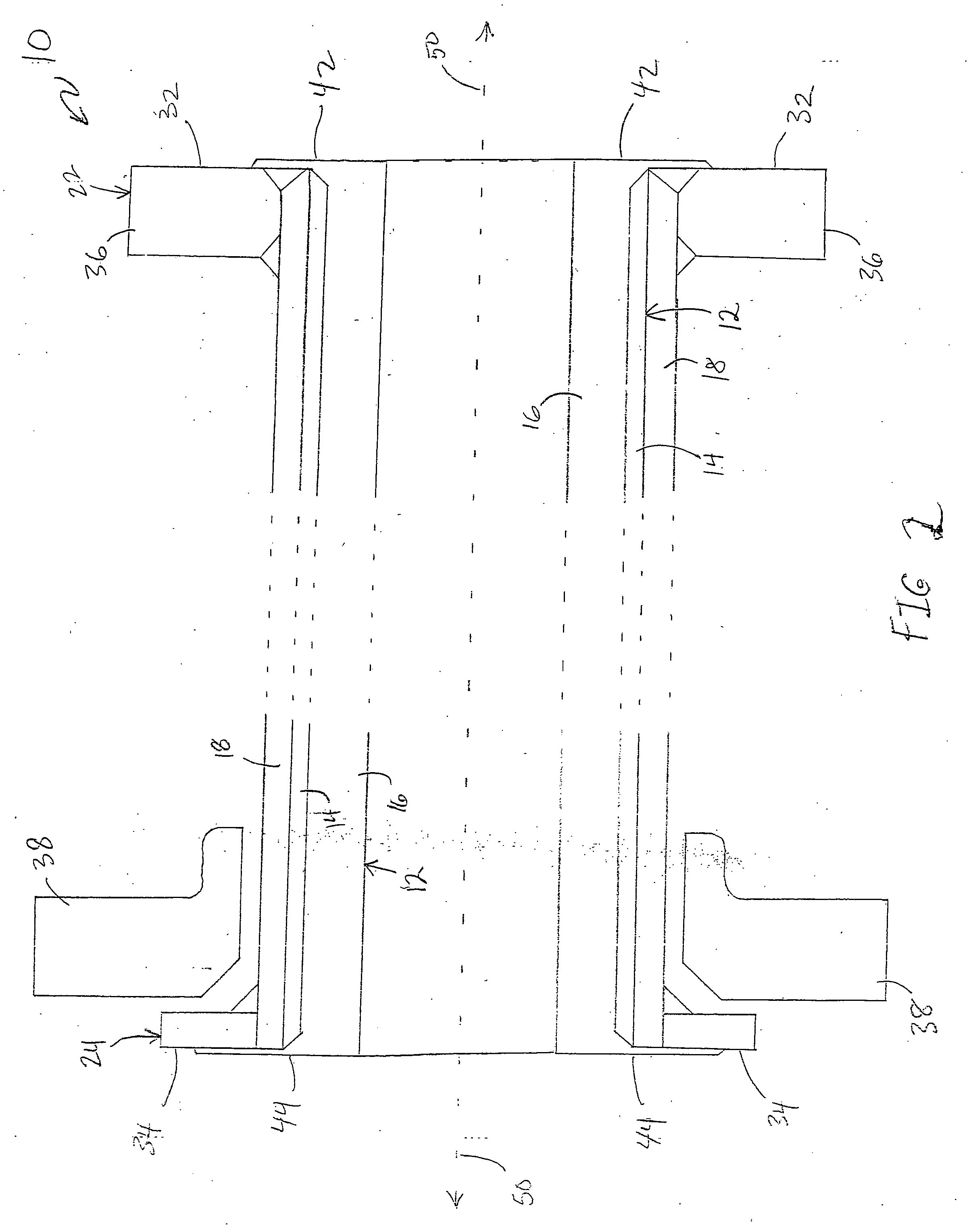
[0017]FIG. 1 illustrates a perspective, cutaway view of a lined pipe 10 with liner 12, according to one illustrative embodiment. FIG. 2 illustrates a side, cross sectional, cutaway view of the lined pipe 10 with liner 12, according to one illustrative embodiment. Liner 12 includes both a rubber liner portion 14 adhered to an inner surface of pipe portion 18, and a polyurethane liner portion 16 adhered to and covering rubber liner portion 14. Lined pipe 10 has a first end 22 and a second end 24 opposite the first end 22. First end 22 includes pipe end surface 32 and polyurethane end surface 42 (both depicted only in FIG. 2) and slip-on flange 36. Second end 24 includes pipe end surface 34, polyurethane end surface 44, and lap joint flange 38. FIG. 2 also depicts end caps 66 and 68 for attaching to first end 22 and second end 24, respectively. Slip-on flange 36, lap joint flange 38, and end caps 66 and 68 are a few examples of a wide variety of flanges, tooling, and other supplemental...


PUM

PropertyMeasurementUnit
diameteraaaaaaaaaa
depthaaaaaaaaaa
depthaaaaaaaaaa

Abstract

A liner includes a rubber liner portion, and a polyurethane liner portion disposed on a surface of the rubber liner portion. The rubber polyurethane liner can be applied to cover surfaces of process support elements used to transport or handle process material such as tar sand slurry. The rubber polyurethane liner increases the effectiveness and operating lifetimes of such process support elements.

Description

CROSS-REFERENCE TO RELATED APPLICATION [0001] This application claims the benefit of U.S. Provisional Application Ser. No. 60 / 548,003, entitled “RUBBER POLYURETHANE LINER”, filed Feb. 26, 2004, which is incorporated by reference herein.FIELD OF THE INVENTION [0002] The present invention relates to liners, and particularly but not by way of limitation, to liners with a rubber layer and a polyurethane layer. BACKGROUND OF THE INVENTION [0003] There has been a persistent need to transport slurry materials through pipelines. Plain steel pipes were once commonly used for this purpose, but breakdown due to abrasion from the slurry material severely limited the functional lifetime of such a steel pipe. A breakthrough came with the introduction of a rubber liner in the steel pipe, which raised the functional lifetime of a steel pipe by around 500%. Rubber-lined steel became commonly used for pipelines in mining and energy development applications around the world. [0004] However, rubber lin...

Claims


Application Information

Patent Timeline
Patent Type & Authority Applications(United States)
IPC IPC(8): B32B1/08B32B7/12B32B15/06B32B15/08C08J5/12F16J10/04F16L55/16F16L58/10F16L58/18
CPCF16L58/1036F17D1/08B05D3/007F16L58/187Y10T137/0318F16L57/06F17D1/084F17D1/088
Inventor BURKES, DANIEL O.
Owner IRATHANE SYST
Why Eureka
Try Eureka