
Pressure washer with diagnostic indicators

a technology of diagnostic indicators and pressure washers, applied in the field of pressure washers, can solve the problems of accidental tripping, inexperienced users to be malfunctioning, and the ac power to the motor to be cut off, so as to quickly and easily identify the possible

Active Publication Date: 2005-09-01
FNA GROUP INC
View PDF8 Cites 59 Cited by
  • Summary
  • Abstract
  • Description
  • Claims
  • Application Information

AI Technical Summary

Benefits of technology

[0006] It is a related goal of the invention to provide means for assisting the user in checking important operation conditions that affect the operation of the pressure washer, so that the user can quickly and easily identify the possible cause for the apparent malfunction of the pressure washer, and take appropriate measures to correct the problem.

Problems solved by technology

Although an electrical pressure washer is a relatively simple device, its operation may be affected by various conditions and may appear to an inexperienced user to be malfunctioning even if the machine is actually in good shape.
A GFCI, however, may sometimes be accidentally tripped, and the AC power to the motor will be cut off as a result.
Nevertheless, an inexperienced user who is unaware of the existence and / or function of the GFCI may think that pressure washer is broken.
A user, however, may not know or remember to check that the pressure washer is in the chemical suction mode and may jump to the conclusion that the pressure washer is defective.
Also, the pressure washer will not work properly if the AC voltage supplied to it is low, which may happen if the user plugs the pressure washer into a long extension cord, which introduces a substance voltage drop due to the large amount of current drawn by the pressure washer.
Thus, inexperienced users often find it difficult to identify the reasons why their electrical pressure washers do not work as expected.
Such difficulties present a serious problem to the manufacturer of the pressure washers due to the increased cost for providing consumer services.
When a user plugs in a newly purchased pressure washer and does not get the expected high-pressure water jet, he may think that the machine is defective and decide to return it to the store where he bought it.
The allegedly bad machine is then returned the manufacturer even if it is fully functional.

Method used


Image

  • Pressure washer with diagnostic indicators
  • Pressure washer with diagnostic indicators
  • Pressure washer with diagnostic indicators

Examples


Embodiment Construction

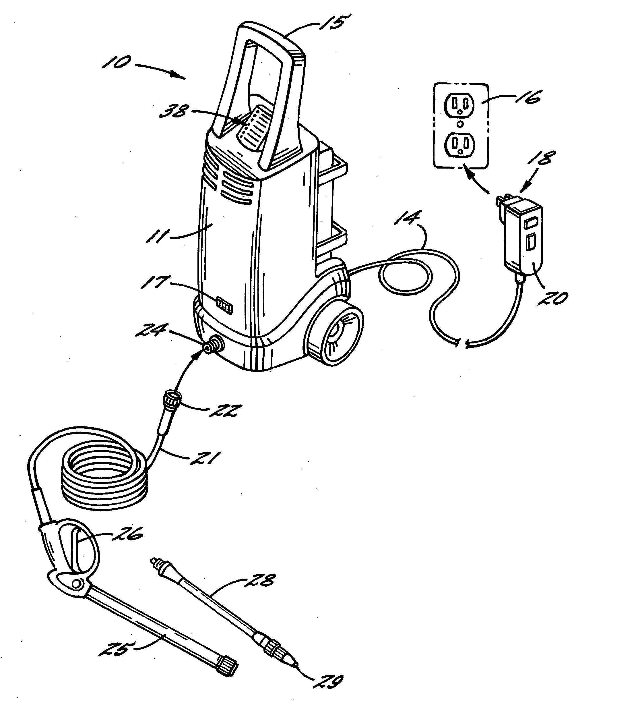
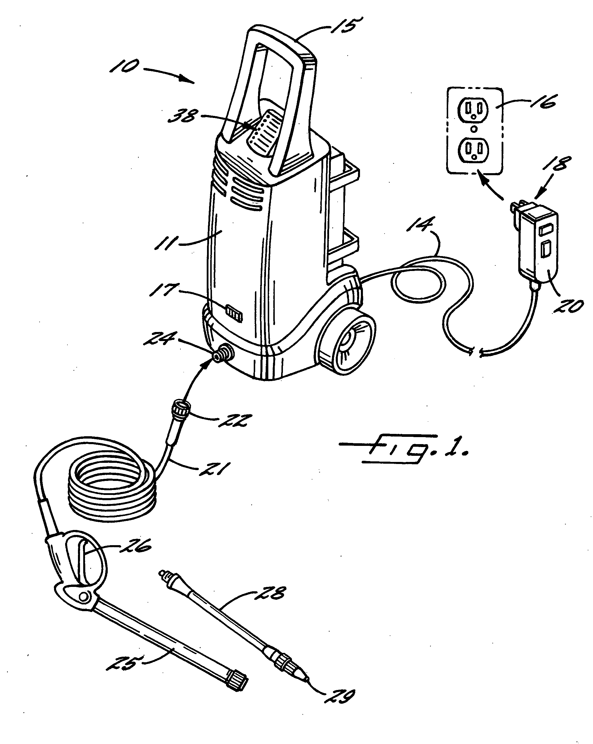
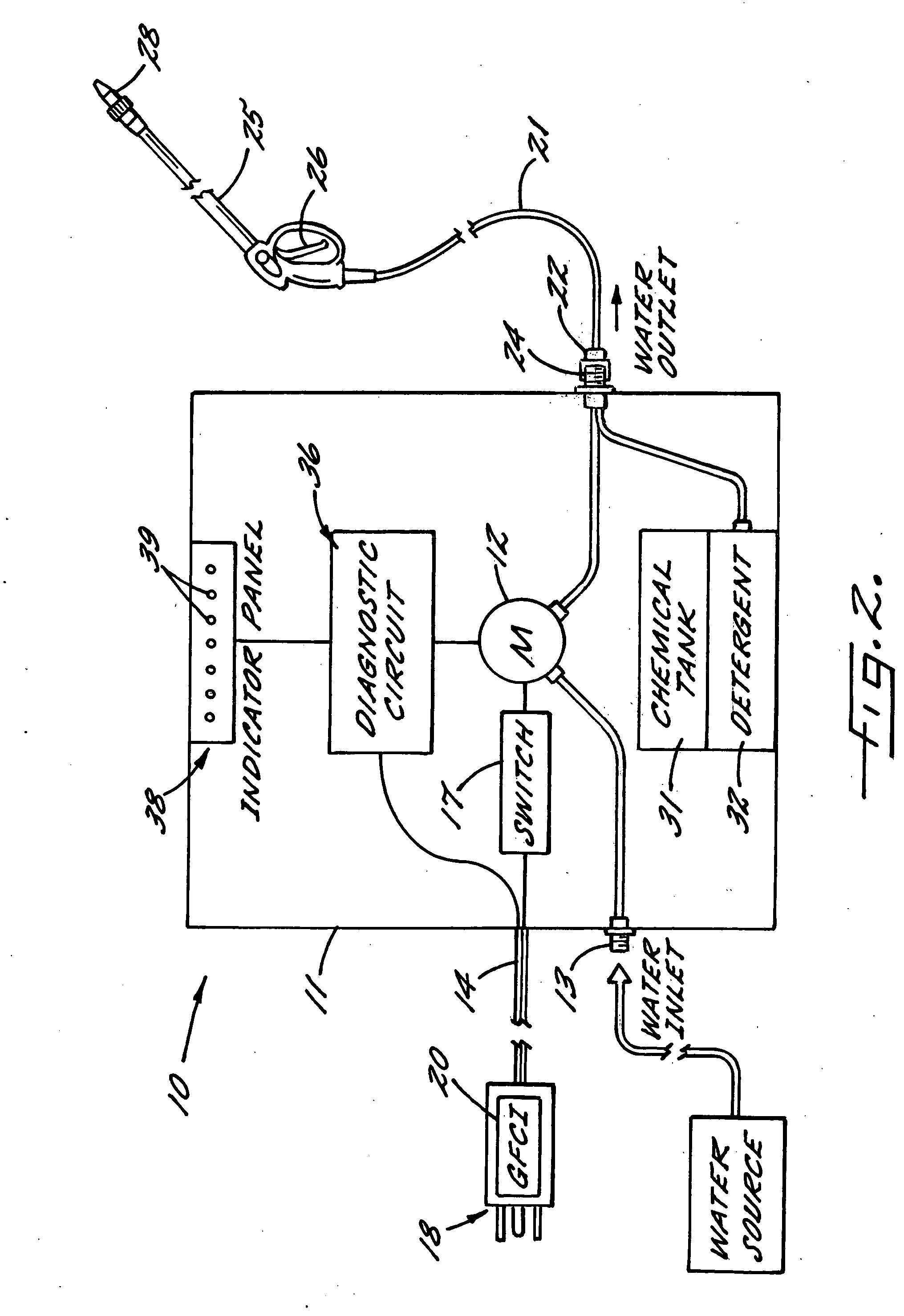
[0016] Turning to the drawings and referring first to FIG. 1, an electrical pressure washer 10 in an embodiment of the invention includes a housing 11 that contains an electrical motor 12 (FIG. 2) for pressurizing water received from a low-pressure water source through a water inlet 13 (FIG. 2) to provide an output high-pressure water stream. A power cord 14 of a pre-selected length connects the pressure washer to an AC outlet 16 from which the pressure washer draws the power needed for operating the motor. An on / off switch 17 on the housing 11 of the pressure washer is used to turn the pressure washer on or off by connecting or breaking the AC power to the motor. On the distal end of the power cord 14 is an AC plug 18 to be plugged into a receptacle of the AC outlet 16. In the illustrated embodiment, the power cord includes a ground fault circuit interrupter (GFCI) 20 that is integrated with the AC plug 18. The GFCI is not required, however, in regions where the electrical safety c...


PUM


Abstract

An electrical pressure washer includes a diagnostic circuit for detecting operation conditions that may affect the normal operation of the pressure washer, and a plurality of indicators indicating the detected operation conditions, such as ground fault, low pressure, overheating, etc. A voltage drop across the power cord of the pressure washer is monitored and used to identify several of the operating conditions. A way of connecting and controlling light-emitting diodes used as indicator lights is provided to allow energy-efficient operation of the indicator lights.

Description

TECHNICAL FIELD [0001] This invention relates generally to pressure washers, and more particularly to a pressure washer that has indicators for indicating operating conditions of the pressure washer to provide diagnostic information to a user. BACKGROUND OF THE INVENTION [0002] A pressure washer is a device that outputs a high-pressure jet of water that can be used to wash surfaces such as wood, tile, concrete, etc. Many pressure washers are powered by electricity and designed for household and light commercial use. Such an electrical pressure washer typically includes an electrical motor for pressurizing water from a low-pressure source (e.g., a garden hose) to a much higher pressure. The pressurized water then goes through a flexible hose to an application wand (or lance), which is fitted with a nozzle with a fixed or variable aperture and has a trigger for turning high-pressure water jet on or off. To enhance the cleaning power of the water stream, some pressure washers have a ch...

Claims


Application Information

Patent Timeline
IPC IPC(8): B08B3/00B08B3/02
CPCB08B3/026B08B2203/0282B08B2203/0217B08B2203/0258
Inventor ALEXANDER, GUSHANSEN, MIKE C.
Owner FNA GROUP INC
Learn More