Structure of a fixed and turning connecting shaft

a technology of connecting shaft and structure, which is applied in the direction of screwdrivers, wrenches, rotary machine parts, etc., can solve the problems of only working shafts, difficult to reach, and not being able to operate quickly, and achieve the effect of stably positioning capability

Inactive Publication Date: 2005-09-01
CHANG SHENG MING
View PDF6 Cites 4 Cited by
  • Summary
  • Abstract
  • Description
  • Claims
  • Application Information

AI Technical Summary

Benefits of technology

[0004] The present invention of an Improved Structure of a Fixed and Turning Connecting Shaft mainly comprises a connecting shaft and a socket, when the socket is sleeving on the connecting shaft, the socket can work on both straight and angle turning manners with stably positioning capability. It also allows speedily switch between operating in straight and angle turning manners.

Problems solved by technology

This type of conventional torque shaft can only work on a straight line and if the socket need to be locked is located away from the straight line, it will make it difficult to reach.
It is not convenient to adjust a steel ball 913, so that when sleeving with the socket, it will not be easy to operate speedily.
But when it operates in the manner of angle turning, the connection between the connecting shaft and the socket depends only on a simple sleeving and insertion mechanism, there is no element to help on positioning, if the operating angle is not suitable for the assignment, the socket will easily fall apart from the connecting shaft.
Thus will affect safety of using the tool.

Method used


Image

  • Structure of a fixed and turning connecting shaft
  • Structure of a fixed and turning connecting shaft
  • Structure of a fixed and turning connecting shaft

Examples


Embodiment Construction

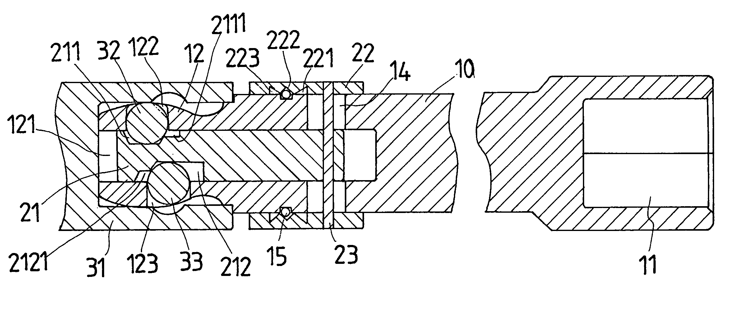
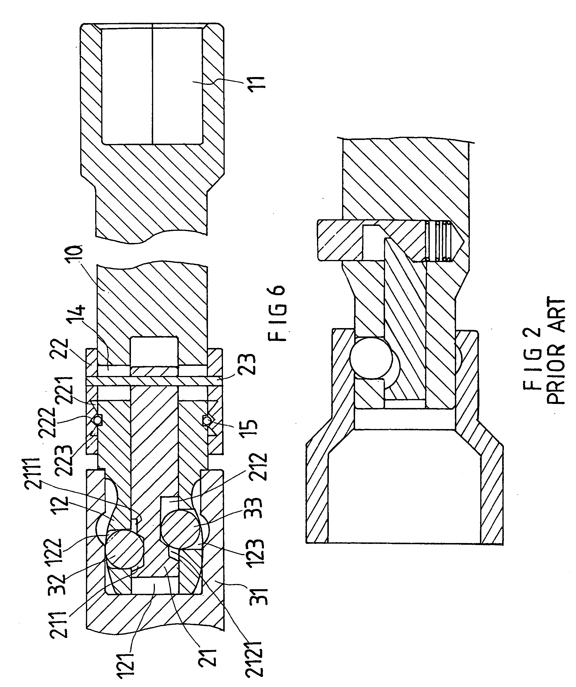
[0015] Referring FIGS. 5 to 8, the present invention of an Improved Structure of a Fixed and Turning Connecting Shaft mainly comprises a connecting shaft 10 for a pneumatic tool (not shown in the Figs.), and a speedily assembly 20 for connecting to the connecting shaft 10 at a suitable location.

[0016] The connecting shaft 10 is in longitudinal bar shape, its one end having a fixed connecting part 11 for connecting to a pneumatic tool with driven power, another end is a connecting part 12 for sleeving a socket 31, a shoulder 13 in corresponding to the socket 31 is disposed between the connecting part 12 and the connecting shaft 10. The fixed connecting part 11 is a hole itself for the axial part (not shown in the Figs.) of the pneumatic tool to connect with. The connecting part 12 is curve in shape, an axial hole 121 is disposed inside along its axis, ball holes 122 and 123 are disposed on each side of the connecting part 12 respectively and are connected with the axial hole 121. Th...


PUM


Abstract

The present invention of an improved structure of a fixed and turning connecting shaft having a connecting shaft with a speedily assembly disposed on it, two ends of the connecting shaft are a fixed connecting part and a connecting part for sleeving a socket, the connecting part is in curved part, a shoulder for connecting to the inner circumference of the socket is disposed between the connecting part and the connecting shaft, the purpose of the shoulder is for the connecting shaft to be able to turn or position with the socket, an axial hole is disposed inside the connecting part for a axial rod to insert into, a ball hole is disposed on each side of the connecting part and the two ball holes are connected to the axial hole, a steel ball is inserted into each ball hole, when the axial rod moves, it will also drives the two steel balls to move, one end of the axial rod is connected to a sliding control element, so that the sliding control element will drive the axial rod to move together on the axis, so as to control the two steel balls to allow the socket to turn upon the connecting shaft or to engage together in position.

Description

BACKGROUND OF THE INVENTION [0001] Conventional power driven tool for socket structure mainly includes two methods, one is by manual and the other is by electrical power. Electrical tools are usually connected to pneumatic power source to take advantage of the output of compression air to provide constant torque to achieve locking assignments. Pneumatic tools usually uses torque connecting shafts to output torque to achieve locking purpose. [0002] Referring to FIG. 1, conventional torque connecting shaft 91 having a protruded sleeving part 911 and a sleeving hole 912 disposed at each end of the shaft, for connecting to a pneumatic tool and for sleeving a socket. This type of conventional torque shaft can only work on a straight line and if the socket need to be locked is located away from the straight line, it will make it difficult to reach. Besides, when the torque connecting shaft 91 is connecting with the socket, the protruded sleeving part 911 engages with the socket. It is not...

Claims


Application Information

Patent Timeline
Patent Type & Authority Applications(United States)
IPC IPC(8): F16D1/12F16D3/20
CPCF16D3/20Y10T403/592Y10S464/901
Inventor CHANG, SHENG-MING
Owner CHANG SHENG MING
Why Eureka
Try Eureka