A multifunctional working device for interior design
A technology for interior design and work equipment, which is applied to computer workstation tables or desks, applications, home appliances, etc. It can solve the problems of large touch display table, untouchable display table carrying work display, and inability to fold and retract. , to achieve the effect of popular and shocking expression, good display effect and reducing cumbersome and complicated effects
- Summary
- Abstract
- Description
- Claims
- Application Information
AI Technical Summary
Problems solved by technology
Method used
Image
Examples
Embodiment 1
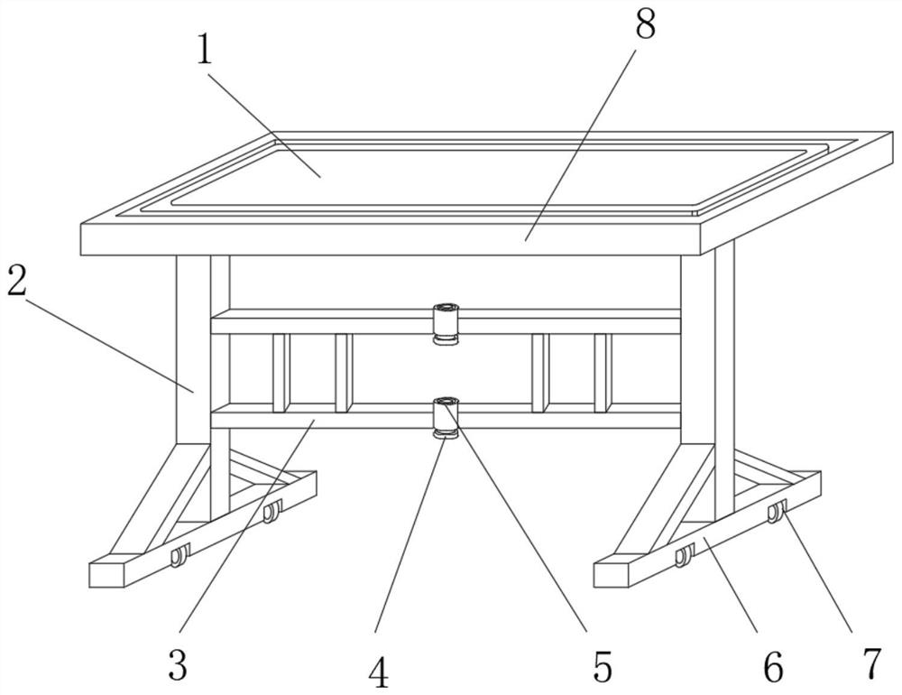
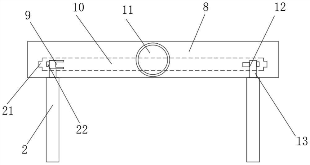
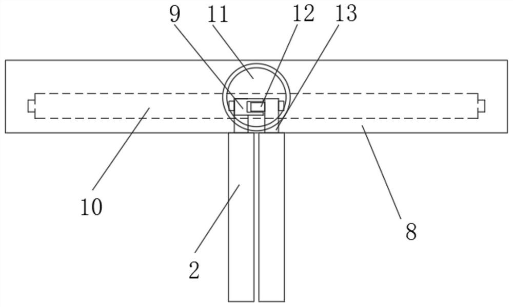
[0031] see Figure 1 to Figure 5 , the present invention provides a technical solution: a multifunctional working device for interior design, including a connecting base 8, a touch display screen 1 located in the middle of the connecting base 8, and two support columns 2 located at the bottom of the connecting base 8, only need According to needs, the work is operated and designed through the touch display 1, and can be displayed through the touch display 1. The touch display 1 can be flipped through the bearing, so that the gap between the touch display 1 and the connecting seat 8 The included angle is adjusted so that the display effect of the touch display screen 1 is better. The use and adjustment angle of the touch display screen 1 are common knowledge of those skilled in the art.
[0032] The middle of the two supporting columns 2 is fixedly connected with two fixed horizontal columns 3, and the two fixed horizontal columns 3 are fixedly connected with multiple columns. ...
Embodiment 2
[0039] see Figure 1 to Figure 6 , the bottom end of the connection seat 8 is provided with a buffer mechanism, the buffer mechanism includes a buffer plate 14, the surface of the buffer plate 14 is fixedly connected with a buffer layer 19, the buffer plate 14 is connected and fixed with the connection seat 8 by a plurality of buffer springs 17, and the shock absorber The spring 17 is an elastic material, which will deform after being subjected to an active force, and return to its original state after losing the active force. The surface of the connecting seat 8 is provided with a receiving groove 18 used in conjunction with a plurality of damping springs 17, and the cross section of the receiving groove 18 is It is circular, and the diameter of the storage groove 18 is greater than the diameter of the cushioning spring 17. The cushioning spring 17 is located in the storage groove 18, so that the cushioning spring 17 can be stored in the storage groove 18, reducing the occupat...
Embodiment 3
[0041] see Figure 1 to Figure 6 , the top of the connecting column 13 is provided with a positioning mechanism, the positioning mechanism includes a magnet 22, the magnet 22 is located on the top side of the connecting column 13, the inside of the connecting seat 8 is provided with a positioning hole 21 used in conjunction with the magnet 22, the cross section of the magnet 22 It is rectangular, and the shape and size of the magnet 22 is consistent with the shape and size of the positioning hole 21. The gap between the two is used together. When the touch display table is in a normal working state, the magnet 22 and the positioning hole 21 are in a tight fit state, thereby increasing the touch. The stability of the control display table reduces the shaking of the touch display table.
[0042] In the present invention, when the touch display table is in working condition figure 1 , the positioning bolt 4 and the fixed bearing 5 are in a fixed state, the fixed horizontal colum...
PUM
 Abstract
Description
Claims
Application Information
 - R&D
- Intellectual Property
- Life Sciences
- Materials
- Tech Scout
- Unparalleled Data Quality
- Higher Quality Content
- 60% Fewer Hallucinations
Browse by: Latest US Patents, China's latest patents, Technical Efficacy Thesaurus, Application Domain, Technology Topic, Popular Technical Reports.
© 2025 PatSnap. All rights reserved.Legal|Privacy policy|Modern Slavery Act Transparency Statement|Sitemap|About US| Contact US: help@patsnap.com


